
Removable medical implant closure

a medical implant and closure technology, applied in the field of removable medical implant closures, can solve the problems of over-torque of the inability of the driving tool to accidently drive both heads, and the inability to over-torque the closure upon installation, etc., and achieve the effect of low profile, easy use and inexpensive production

Inactive Publication Date: 2005-12-01
JACKSON
View PDF35 Cites 145 Cited by
  • Summary
  • Abstract
  • Description
  • Claims
  • Application Information

AI Technical Summary

Benefits of technology

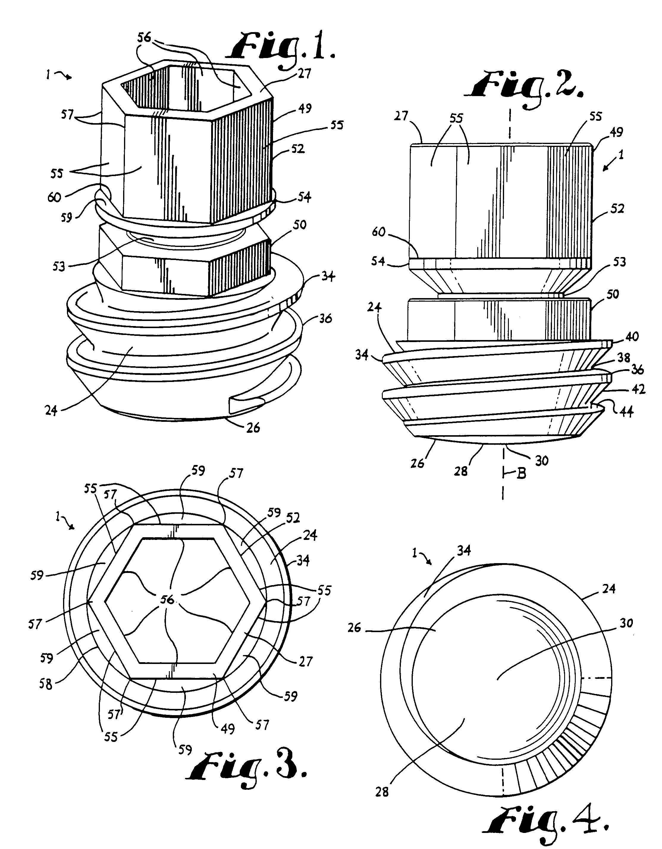
The invention is a closure and locking member for a medical implant, such as a bone screw or hook, used in spinal implant systems. The closure is designed to capture and fix a rod or other elongate structure in the implant. It includes a break-off portion that is torqued by a driving tool until a predetermined torque is achieved, at which point it breaks away from the closure. The closure also has a second driving or removal head that prevents accidental over-torquing and allows for the same driving tool to be used with the removal head. The break-off portion and the second driving or removal head have a driving feature that is shaped and sized to receive a driving tool. The closure provides flexibility during surgery and a low profile.

Problems solved by technology

Thus, the driving tool cannot be accidently used to drive both heads and over-torque the closure upon installation.

Method used


Image

  • Removable medical implant closure
  • Removable medical implant closure
  • Removable medical implant closure

Examples


Embodiment Construction

[0024] As required, detailed embodiments of the present invention are disclosed herein; however, it is to be understood that the disclosed embodiments are merely exemplary of the invention, which may be embodied in various forms. Therefore, specific structural and functional details disclosed herein are not to be interpreted as limiting, but merely as a basis for the claims and as a representative basis for teaching one skilled in the art to variously employ the present invention in virtually any appropriately detailed structure.

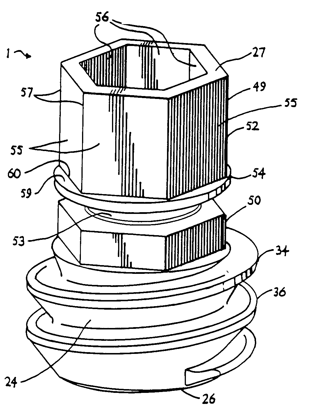
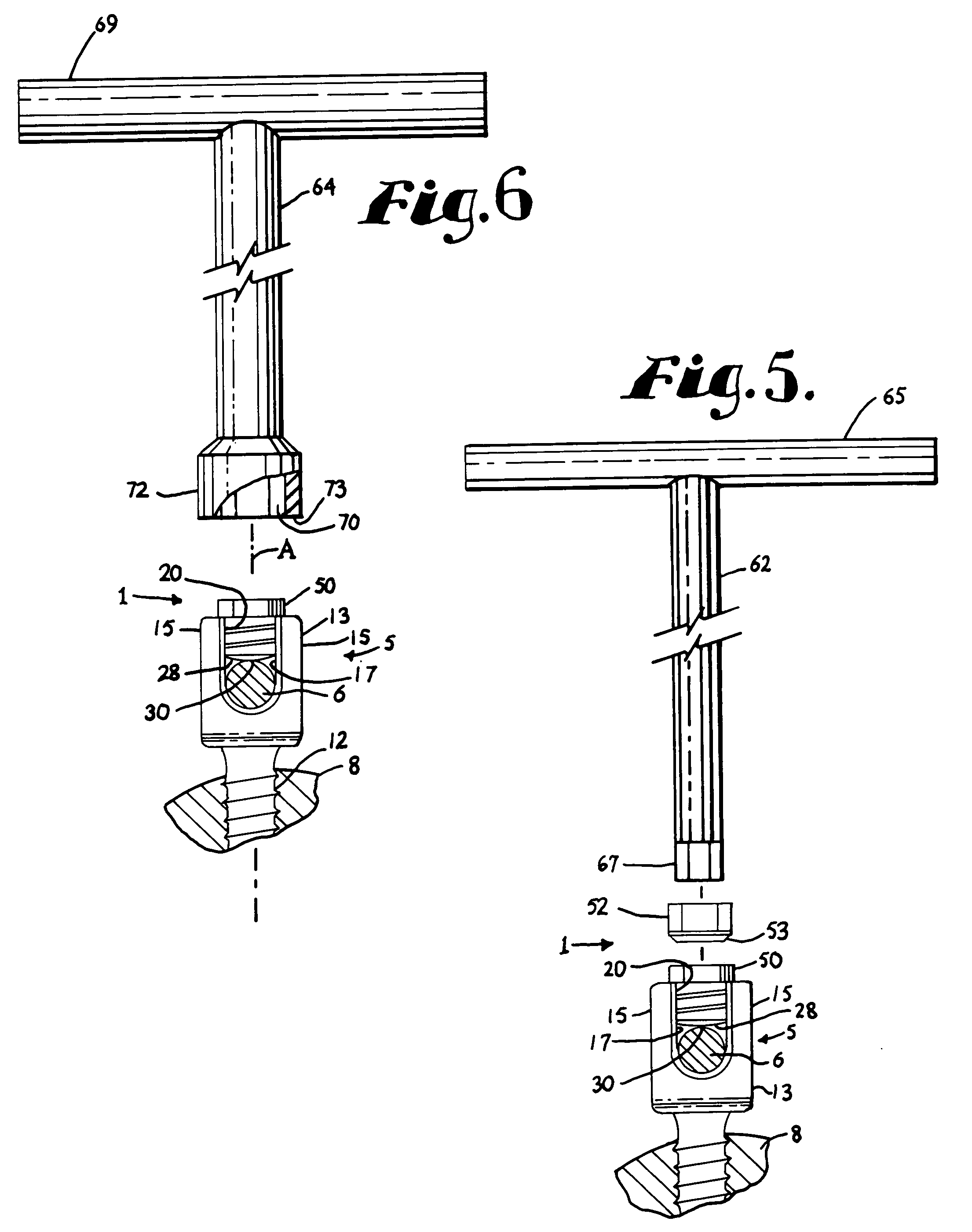
[0025] With reference to FIGS. 1-6, the reference numeral 1 generally designates a closure according to the present invention. With reference to FIGS. 5 and 6, the closure 1 is shown utilized to close a top of a polyaxial medical implant bone screw, generally 5, and capture an elongate member or rod 6, the bone screw 5 and the rod 6 being operably incorporated in an overall spinal implant system for correcting degenerative conditions, deformities, injuries,...


PUM


Abstract

A closure for use in conjunction with an open receiver of a medical implant for capturing and locking a rod member in the implant includes a radially outward threaded cylindrical body sized and shaped to be threadably received between two arms of a head of the implant. The closure also includes a driving head and a coaxial removal head. The driving head includes an internal driving feature and may include an external driving feature. The driving head breaks away from the body at a predetermined torque leaving the removal head. In one embodiment, a rim stop is located near a base of the driving head to prevent a tool with a socket for gripping the driving head from inadvertently gripping the removal head during installation and over-torquing the closure. The stop is removed with the driving head, leaving the removal head that may be received by the same socket tool used for installation.

Description

CROSS REFERENCE TO RELATED APPLICATION [0001] This is a continuation-in-part of application Ser. No. 11 / 110,405, filed Apr. 20, 2005, which is a continuation-in-part of application Ser. No. 09 / 588,924, filed Jun. 6, 2000, now U.S. Pat. No. 6,884,244.BACKGROUND OF THE INVENTION [0002] The present invention is directed to a closure and / or locking member for use in conjunction with medical implants that have open or closed receivers or heads for receiving rods and the like and, in particular, to such a closure that includes a break-off installation head and a second removal head. [0003] Various medical implants that are used in conjunction with spinal surgery include open receivers or heads that receive rods and other elements of an overall implant system. These implants include bone screws, hooks and related parts that are variously used to produce an overall implant system. The implant system, in turn, provides support or stabilization to a patient's spine to compensate for instabili...

Claims


Application Information

Patent Timeline
Patent Type & Authority Applications(United States)
IPC IPC(8): A61B17/70A61B19/00
CPCA61B17/7032A61B2019/307A61B2019/301A61B2090/037A61B2090/031
Inventor JACKSON
Owner JACKSON
Learn More