Spinal facet fixation device

a technology of facet fixation and spine, which is applied in the direction of osteosynthesis devices, surgical staples, prostheses, etc., can solve the problems of disc herniation or protrusion, and variety of problems or disease states

Inactive Publication Date: 2005-12-01
SUDDABY LOUBERT
View PDF4 Cites 96 Cited by
  • Summary
  • Abstract
  • Description
  • Claims
  • Application Information

AI Technical Summary

Benefits of technology

[0012] In either scenario, the salient feature of the device is the opposable nature of the component elements that function as jaws to bite and hold the separate articular components of the facet joint thereby serving to immobilize them. The jaws of the device in turn have pointed tips or teeth that engage the cortical surfaces of the joint as the jaws are mechanically closed. Unidirectional closure of the fixation device is achieved either through a screw or a ratchet mechanism which prevents opening of the jaws or disengagement of the teeth once the desired degree of crimping has been achieved.

Problems solved by technology

As a result, the stresses acting upon the human backbone (or “vertebral column”), are unique in many senses, and result in a variety of problems or disease states that are peculiar to the human species.
Unfortunately, the repetitive forces which act on these intervertebral discs during repetitive day-to-day activities of bending, lifting and twisting cause them to break down or degenerate over time.
Disruption of a disc's internal architecture leads to bulging, herniation or protrusion of pieces of the disc and eventual disc space collapse.
In addition, loss of disc space height relaxes tension on the longitudinal spinal ligaments, thereby contributing to varying degrees of spinal instability.

Method used


Image

  • Spinal facet fixation device
  • Spinal facet fixation device
  • Spinal facet fixation device

Examples


Embodiment Construction

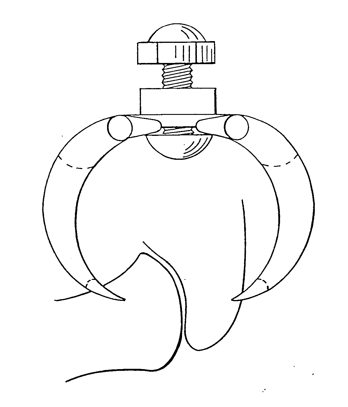
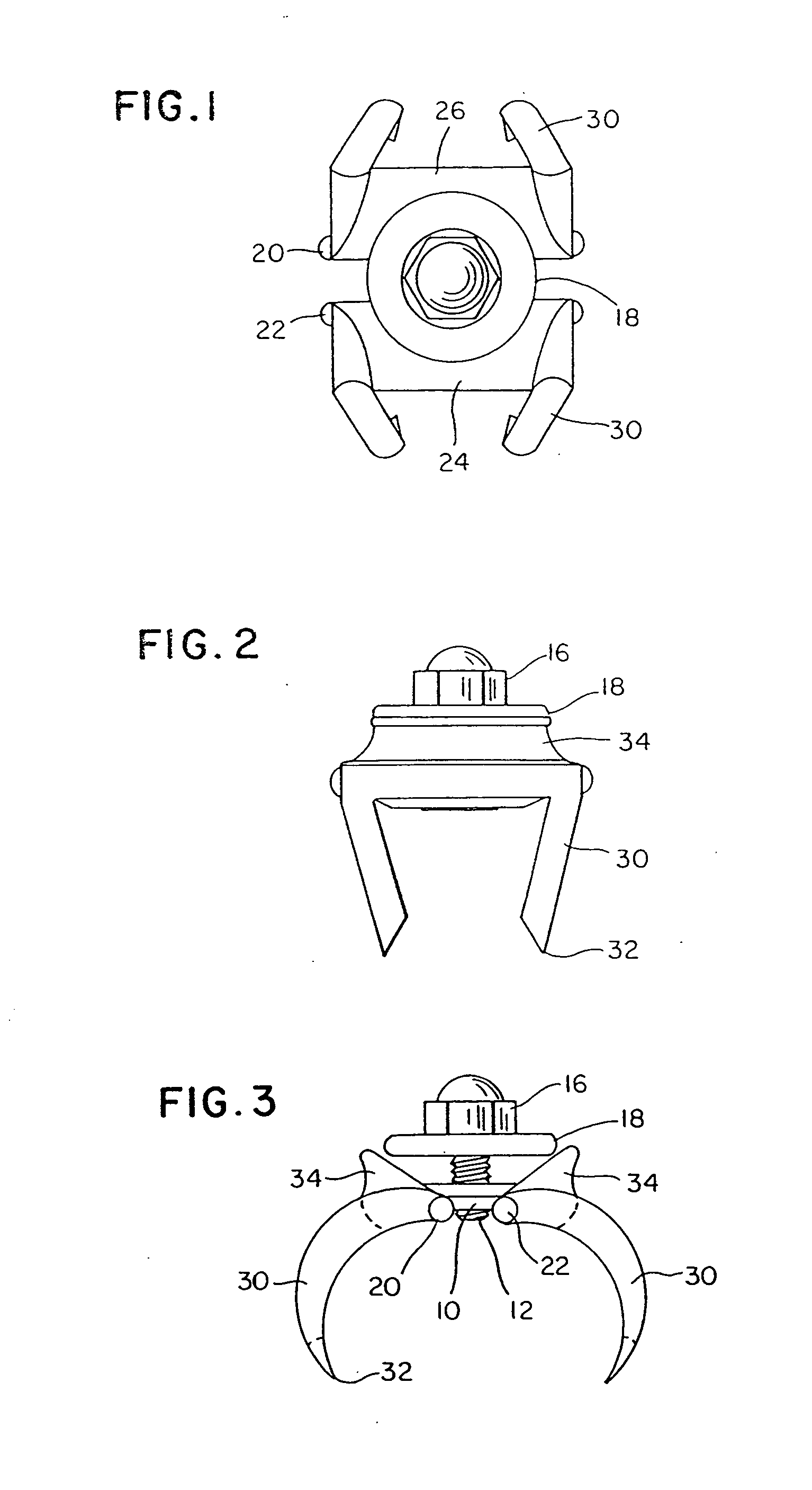
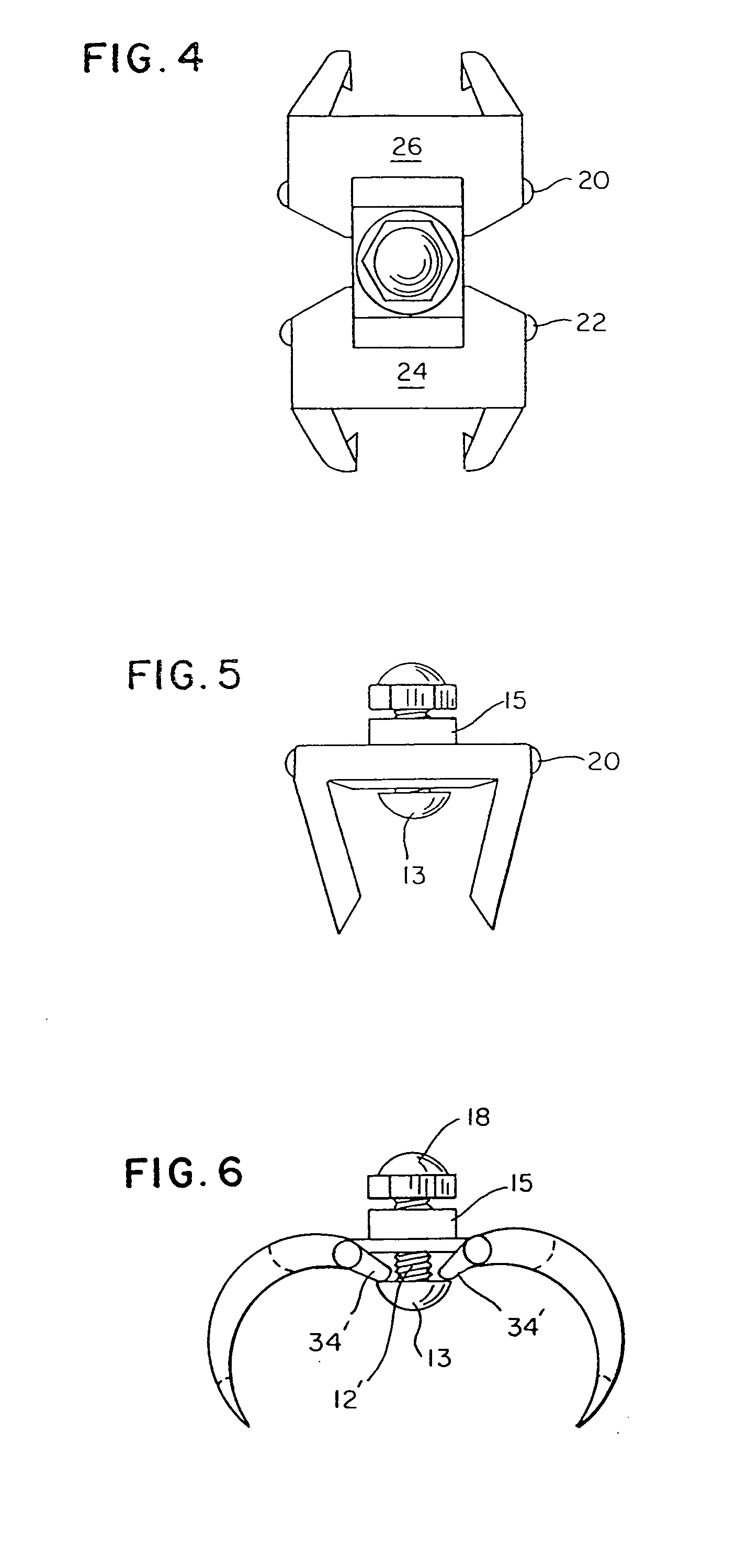
[0026] The spinal facet fixation device shown in FIGS. 1-3 comprises a base member 10 having a threaded post 12 affixed at its center and extending perpendicularly therefrom. A nut 16 having an integral or captive washer 18 thereon is threaded onto the post.

[0027] A pair of pivot pins 20,22 are affixed to the bottom of the base, equally offset from the center. The ends of the pins fit within holes (not shown) formed in respective jaws 24,26. Each of the jaws has one or more curved fingers 30, each terminating at a pointed tip 32.

[0028] The upper surface of each jaw has an upwardly protruding cam 34 (FIG. 3) designed to bear against the washer. When the nut 18 is turned clockwise, it advances down the post, and the washer 16, bearing against the cams 34 on either side, forces the jaws to pivot downward, bringing their pointed tips 32 closer together.

[0029] To draw a facet joint together, a surgeon places the pointed tips of the jaws against neighboring facets (FIG. 12), and then t...


PUM


Abstract

A spinal facet fixation device includes a pair of jaws hinged on a common base. A threaded actuator bears against a cam surface on the jaws to draw the points of the jaws together. A surgeon applies the opposed points to respective facets of vertebral elements, and then tightens the actuator to draw the facets together.

Description

[0001] This is a continuation of application Ser. No. 10 / 230140, filed Aug. 29, 2002.BACKGROUND OF THE INVENTION [0002] This invention relates to the field of orthopedic spinal fusion surgery and particularly to the process of interarticular facet fixation or fusion, serving to stabilize adjacent vertebral elements, thereby facilitating the development of bony union between them and thus long term spinal stability. [0003] Of all animals possessing a backbone, human beings are the only creatures who remain upright for significant periods of time. From an evolutionary standpoint, this erect posture has conferred a number of strategic benefits, not the least of which is freeing the upper limbs for purposes other than locomotion. From an anthropologic standpoint, it is also evident that this unique evolutionary adaption is a relatively recent change and as such has not benefitted from natural selection as much as have backbones held in the horizontal attitude. As a result, the stresses ...

Claims


Application Information

Patent Timeline
Patent Type & Authority Applications(United States)
IPC IPC(8): A61BA61B17/56A61B17/58A61B17/70
CPCA61B17/7064
Inventor SUDDABY, LOUBERT
Owner SUDDABY LOUBERT
Why Eureka
Try Eureka