
Disposable safety cutting tool

a cutting tool and safety technology, applied in the field of disposable safety cutting tools, can solve the problems of incisions being prone to jagged and irregular, inconvenient to use by and less than ideal incision design in many instances, so as to achieve the effect of convenient and effective use for surgeons or other professionals

Inactive Publication Date: 2005-12-01
MILESTONE SCIENTIFIC INC
View PDF4 Cites 60 Cited by
  • Summary
  • Abstract
  • Description
  • Claims
  • Application Information

AI Technical Summary

Benefits of technology

The present invention provides a safety scalpel or cutting tool that can be easily and effectively used by surgeons or professionals. The scalpel has a rounded or cylindrical housing and a cutting head that can be advanced and retracted. The cutting head is biased towards its retracted position to prevent injury. The coupling that advances and retracts the cutting head is designed to automatically rotate it, and a control means is provided to move the cutting head between its positions. The cutting head can be a flat blade or a thin sleeve for obtaining biopsies.

Problems solved by technology

Most bladed devices of this nature are “flat” in design in which holding the bladed instrument proves to be difficult to perform a curving or rounding incisions thus resulting in a less then ideal incision design in many instances.
Incisions can therefore be jagged and irregular.
A “flat” design handle requires greater wrist movement to compensate for the handle design which can lead to awkward positioning of the hand during critical surgical movements.
Moreover, inherently scalpels have sharp edges that may cause pricks, cuts, scratches and other similar problems to the health care provider handling the scalpel, or others.
Any cutaneous cut is undesirable because it could be painful, can result in bleeding and scarring.
Even a small cut may take a long time to heal and be extremely inconvenient.
Moreover, once used on a patient, the blade could be contaminated.
Of course, in today's environment there is a great deal of concern regarding any cuts or punctures to the skin of a health care provider that can cause contamination.
In the second position, the shield is disposed over the blade so that the blade cannot be touched and it will be a health threat.
These safety scalpels are difficult to use and they may not provide sufficient safety.

Method used


Image

  • Disposable safety cutting tool
  • Disposable safety cutting tool
  • Disposable safety cutting tool

Examples


Embodiment Construction

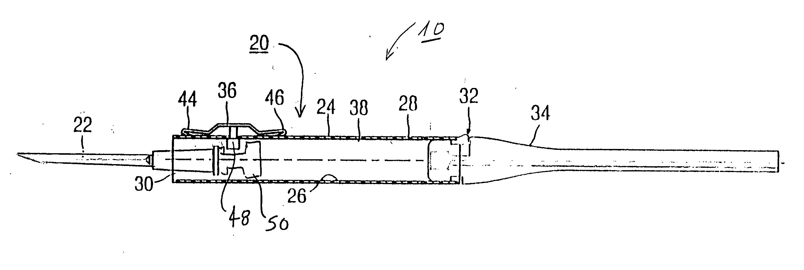
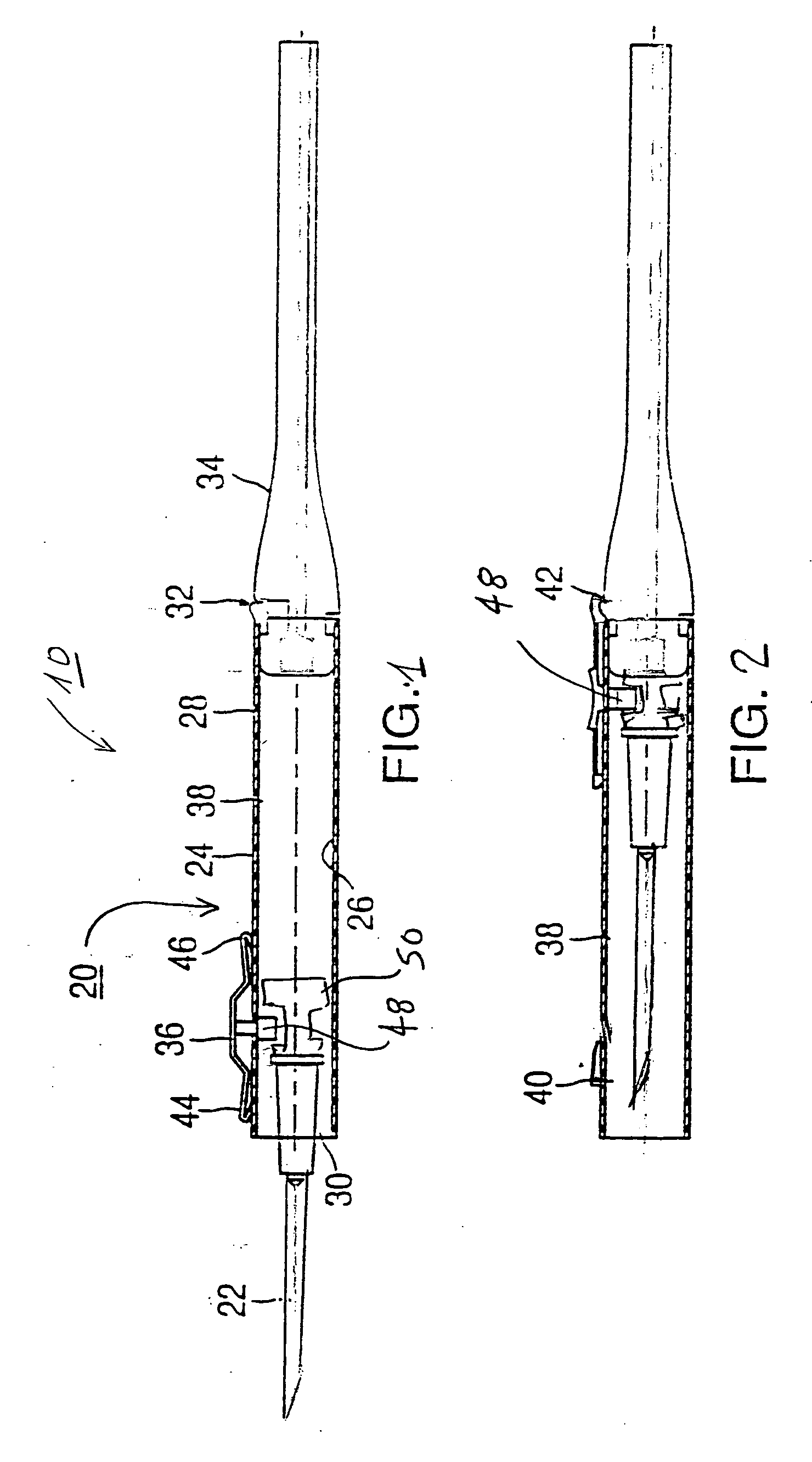
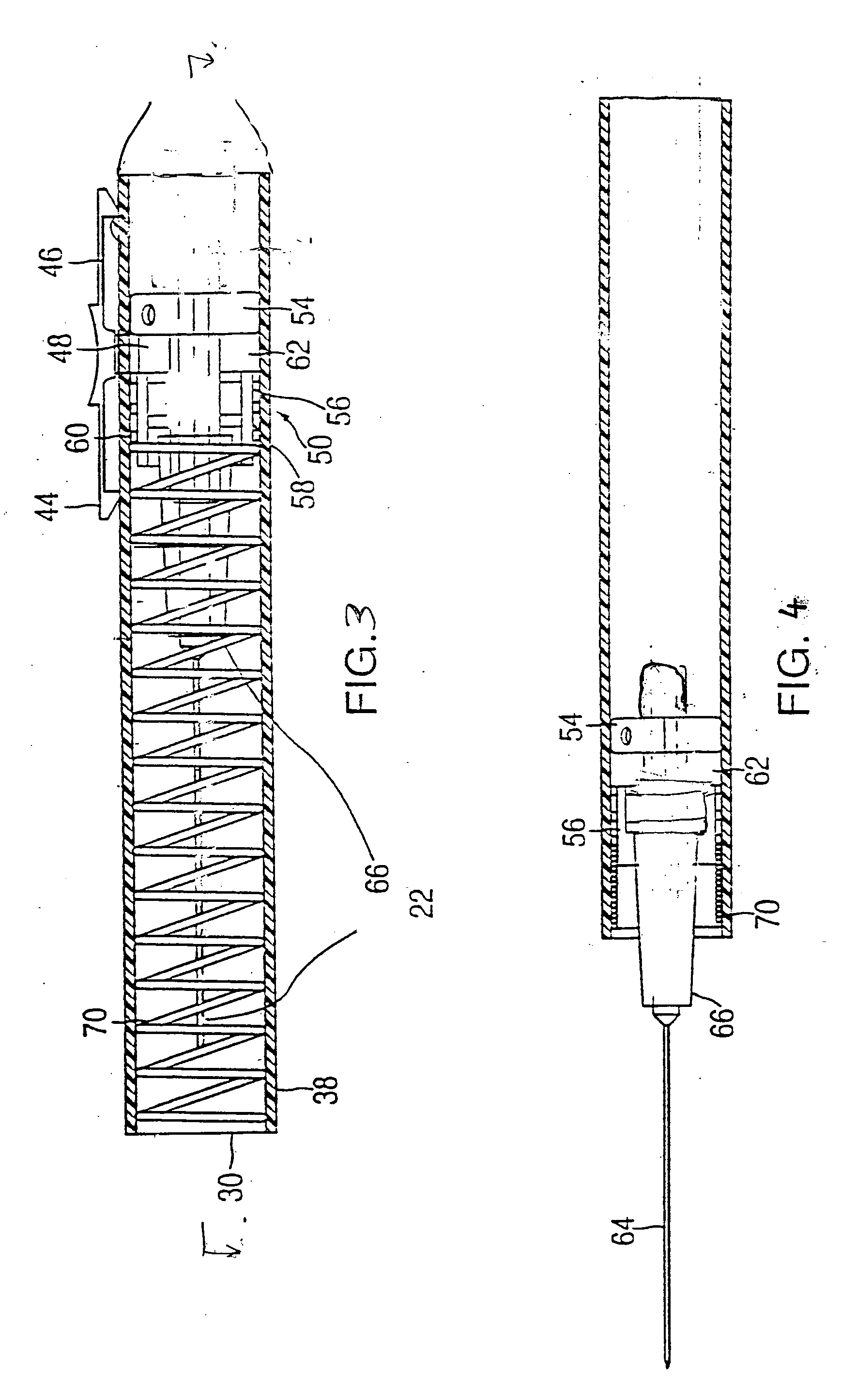
[0029] Referring now to the drawings, a cutting tool such as a safety scalpel 10 constructed in accordance with this invention includes a handle 20 and a cutting head such as a blade 22 attached to the handle 20.

[0030] As shown in FIG. 1, the handle 20 includes in accordance with this invention a tubular housing 24 having a circular or other outer cross section, an internal wall 26, an external wall 28, and two ends 30, 32. Handle 20 further includes an elongated stem 34 provided to balance the handle and make it easier to hold. The stem 34 may be glued to the housing 24, or may be sized and shaped to form an interference fit therewith whereby it can be inserted into the housing 24 or removed at will. The stem 34 may be omitted.

[0031] Mounted on housing 24 there is a button 36 slidable in a longitudinal slot 38 extending through the housing. Housing 24 is provided with a stop 40 at the forward end of slot 38. The rear end 42 of the housing 24 serves as a rear stop for button 36. A...


PUM


Abstract

A safety scalpel is provided that includes a tubular housing, a coupling reciprocating within the housing and holding a cutting head or blade and a control member used to selectively extend said cutting head outwardly of the housing and retracted into the housing. A biasing spring is used to hold the cutting head in a retracted position. In one embodiment a tubular groove on an inner surface of the housing may be used to simultaneously translate the cutting head and rotate it about a longitudinal axis of the housing. The cutting head can be immobilized within the housing by jamming the control tab or by removing the control tab from the housing.

Description

BACKGROUND OF INVENTION [0001] 1. Field of Invention [0002] This invention pertains to a safety bladed device, safety scalpel or other similar cutting tool including a handle and a cutting head, such as a blade, that is selectively extended from the handle and then retracted after use. The total package (i.e. the handle and the cutting head) can be disposed. Alternatively, the cutting head can be disposed and the handle can be used after sterilization. In one embodiment, the cutting head rotates about a longitudinal axis as it is extended. [0003] 2. Description of the Prior Art [0004] Scalpels are used in various surgical procedures to make an incision through the skin of a patient, or to performing other cutting / slicing operations in a patient's body. Most bladed devices of this nature are “flat” in design in which holding the bladed instrument proves to be difficult to perform a curving or rounding incisions thus resulting in a less then ideal incision design in many instances. In...

Claims


Application Information

Patent Timeline
Patent Type & Authority Applications(United States)
IPC IPC(8): A61B17/32
CPCA61B2017/32113A61B17/3211
Inventor HOCHMAN, MARK N.
Owner MILESTONE SCIENTIFIC INC
Learn More