Air no air elastomeric tire

a technology of air-to-air elastomeric tires and elastomeric tires, which is applied in the field of non-pneumatic tires to achieve the effect of increasing the inherent load bearing capacity of the un-inflated and enhancing the load carrying capacity

Inactive Publication Date: 2005-12-08
STEINKE RICHARD A
View PDF28 Cites 5 Cited by
  • Summary
  • Abstract
  • Description
  • Claims
  • Application Information

AI Technical Summary

Benefits of technology

[0018] A proper tire arch-shaped cavity will have a uniform radius taken from a point of origin of the arch that vertically bisects the tire, with a maximum arc of the arch being one hundred seventy (170) degrees and a minimum arch of one hundred forty (140) degrees between rim points of engagement formed in the opposing tire sides whereat the rim ends are fitted. A tire with an arch of up to one hundred seventy (170) degrees and greater than one hundred forty (140) degrees will provide, with the tire at ambient pressure, a very stable side wall junction of the tire side wall to the rim ends, supporting the tire under a load with little tire flexure at its rim junctions.
[0019] The tire inner and outer surfaces around the arch, below the tread, are spaced a like distance apart, providing a uniform wall and tread thickness of tire material. For the tire to support a design load, at an ambient air pressure, the cavity surface is formed to have a uniform arc of from one hundred seventy (170) to at least one hundred forty (140) degrees as taken from points on the opposing tire side walls whereto rim ends are fitted, and with the outer surface of the

Problems solved by technology

Pneumatic tires generally have less mass than a comparable non-pneumati

Method used


Image

  • Air no air elastomeric tire
  • Air no air elastomeric tire
  • Air no air elastomeric tire

Examples


Embodiment Construction

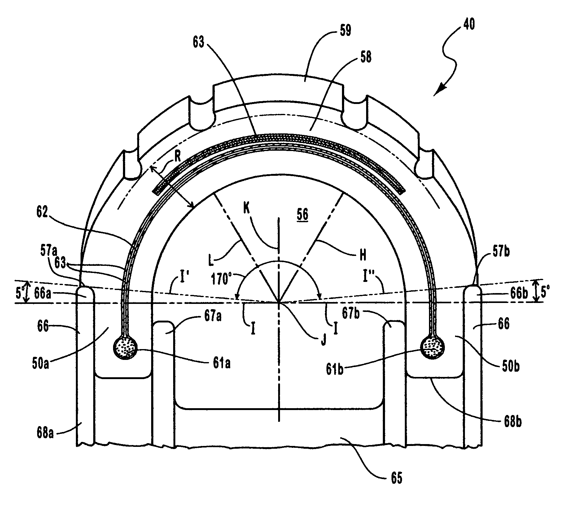
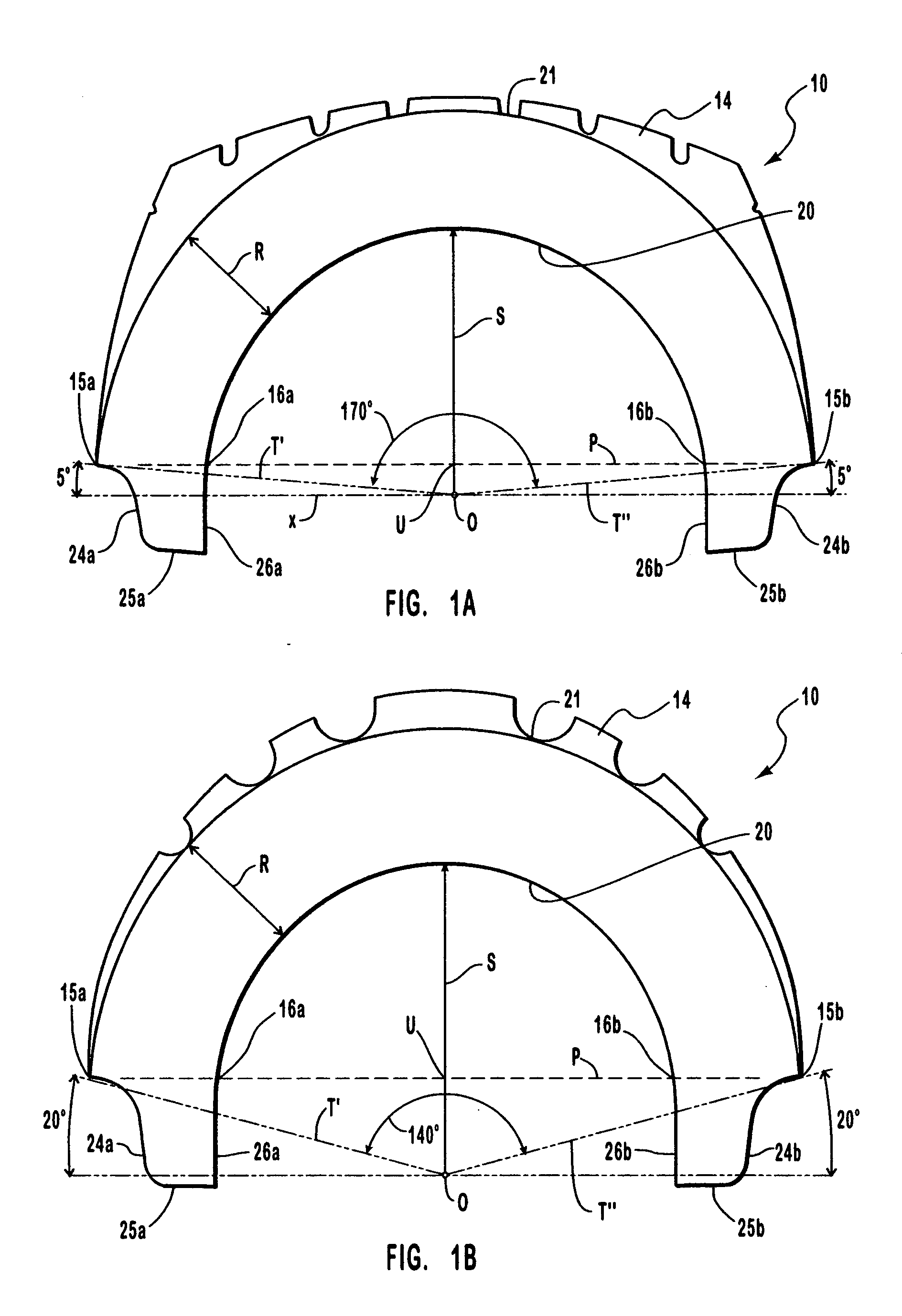
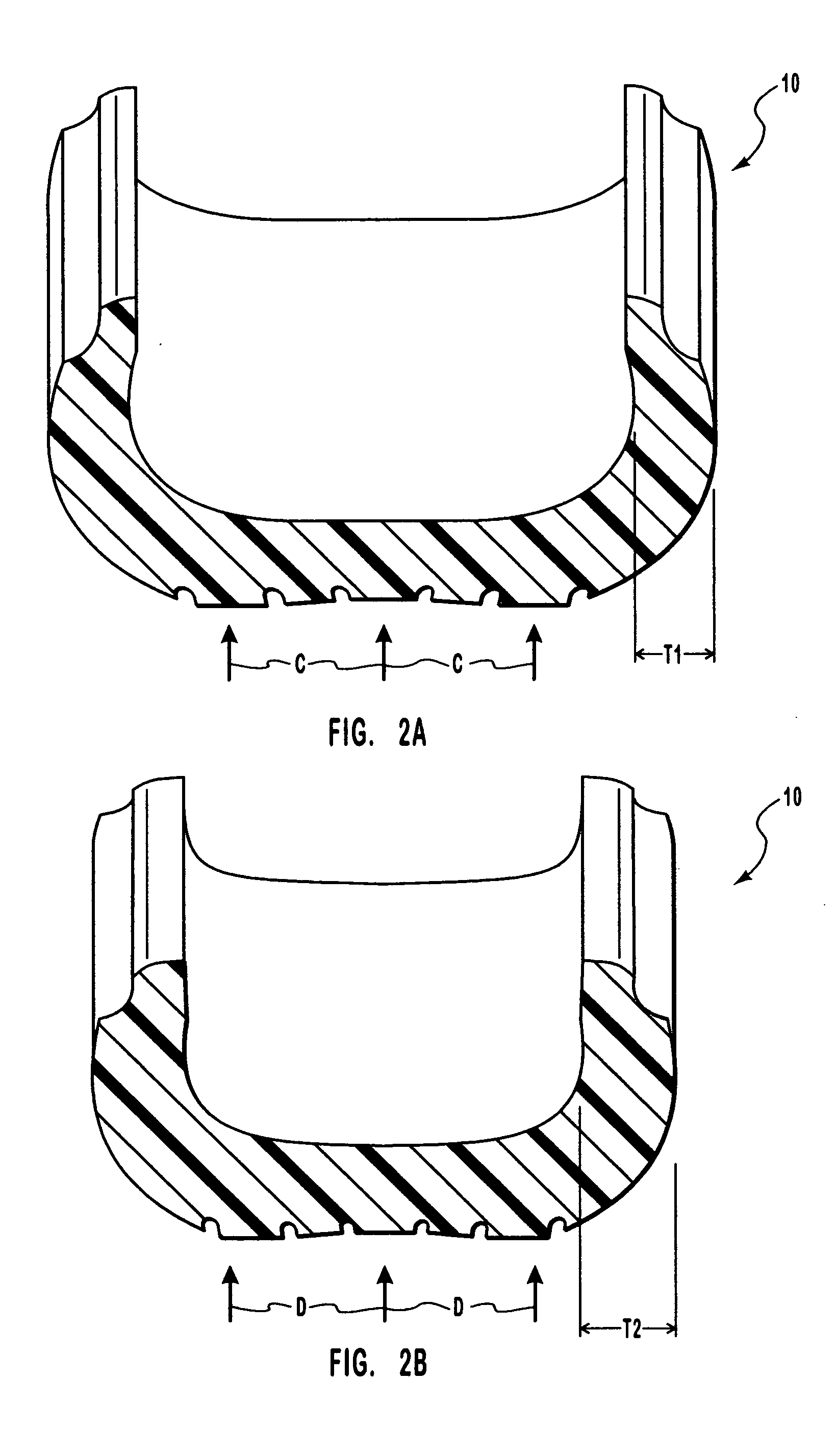
[0033] An automobile tire 10 of the invention is shown in FIGS. 1A, 1B and 3. An automobile tire is shown in FIG. 4 that is like the tire of FIGS. 1A, 1B and 3, but also includes internal beads and a combination of plies and belts, mounted within the tire and secured to a rim at its ends, between the beads. Which embodiments of automobile tires and their unique construction are discussed in detail herein below.

[0034] The tire 10, and the tire embodiment 40 of FIG. 5 of the invention, each includes a casing or body that is preferably formed from an elastomeric material, such as a urethane material, preferably utilizing spin casting methods like those described in apparatus and method patents, U.S. Pat. Nos. 4,855,096; 4,943,323; 5,906,836 and 6,165,397, that the present inventor is a co-inventor of. Though, it should be understood, the invention could be manufactured from other elastomeric materials, such as natural or synthetic rubber, and by other methods and apparatus from that s...


PUM


Abstract

An elastomeric tire for mounting onto a rim that is manufactured by casting or molding methods to include an exterior arch shaped cavity that is centered under and is below the tire tread to have at least one hundred forty (140) degrees and not more than one hundred seventy (170) degrees of arc from one tire rim mounting contact point, around the tire to another tire rim mounting contact point, and with the cavity arch duplicated around the tire interior. A uniform tire wall thickness is provided that is selected for a particular anticipated load as the tire will carry, with the tire side wall ends each maintained at one the rim opposing ends, supporting the load carried by the tire in compression, and with the tire, at atmospheric pressure, providing ride and wear characteristics that are comparable to a pressurized pneumatic tire carrying a like load, and which tire of the invention interior arch-shaped cavity can be pressurized to add to its inherent load supporting character to safely support even greater loads.

Description

[0001] This application is a second continuation-in-part application of an application Ser. No. 09 / 665,604 for an “AIR NO AIR ELASTOMERIC TIRE” filed Sep. 20, 2000, a continuation-in-part application Ser. No. 09 / 943,814 for an “AIR NO AIR ELASTOMERIC TIRE” filed Sep. 4, 2001, and a continuation-in-part application Ser. No. 10 / 412,471 that is abandoned with the entry of this third continuation in part application.BACKGROUND OF INVENTION [0002] 1. Field of the Invention [0003] This invention pertains to non-pneumatic tires for mounting onto a rim as a component of a wheel, and particularly to a tire that is formed, preferably by molding methods, from an elastomeric material, having a center cavity whose walls are capable of bearing a load, allowing the tire to safely support a design load with only air at ambient pressure therein, and the center cavity of which tire can be aired to a desired pressure to support a greater load. [0004] 2. Prior Art [0005] The present invention contempla...

Claims


Application Information

Patent Timeline
IPC IPC(8): B60C1/00B60C3/00B60C3/04B60C5/00B60C5/01B60C7/12B60C7/22B60C9/11B60C15/024B60C17/00
CPCB60C1/0016B60C3/04B60C5/00B60C15/024B60C7/22B60C9/11B60C7/12B60C5/01
Inventor STEINKE, RICHARD A.
Owner STEINKE RICHARD A
Why Eureka
Try Eureka