Thermal activation device and method of conveying sheet material

a technology of activation device and sheet material, which is applied in the direction of lighting and heating apparatus, instruments, recording apparatus, etc., can solve the problems of skew feed and difficulty in forming the adhesive region having an intended width

Inactive Publication Date: 2005-12-08
SEIKO INSTR INC
View PDF4 Cites 6 Cited by
  • Summary
  • Abstract
  • Description
  • Claims
  • Application Information

AI Technical Summary

Benefits of technology

[0026] As described above, according to the thermal activation device and the method of conveying a sheet material in accordance with the present invention, the sheet material is conveyed by taking, as a reference, the conveying speed by the pair of conveyor rollers provided on the conveyor route of the sheet material by the platen roller and the heating means. Accordingly, the sheet material can be prevented from being conveyed while being inclined with respect to the conveying direction thereof owing to the difference in frictional force occurring in the width direction of the sheet material. Hence, according to the present invention, even in the case of thermally activating the heat-sensitive adhesive layer asymmetrically with respect to the centerline of the sheet material in the width direction, the sheet material is prevented from being inclined. Accordingly, the adhesive region and the non-adhesive region can be formed well with the desired widths on the heat-sensitive adhesive layer of the sheet material.

Problems solved by technology

As a result, a difference occurs between the respective conveying speeds v1 and v2 in the width direction by the platen roller 112, and thus there is a problem in that the sheet material 103 is inclined with respect to the conveying direction to cause skew feed.
Accordingly, it has been difficult to form the adhesive region having an intended width on the heat-sensitive adhesive layer of the sheet material 103.

Method used


Image

  • Thermal activation device and method of conveying sheet material
  • Thermal activation device and method of conveying sheet material
  • Thermal activation device and method of conveying sheet material

Examples


Embodiment Construction

[0035] Specific embodiments of the present invention will be described below with reference to the drawings.

[0036] First, a label issuing instrument to be used in the case of issuing a label attached to an article for displaying various types of information on the article will be briefly described.

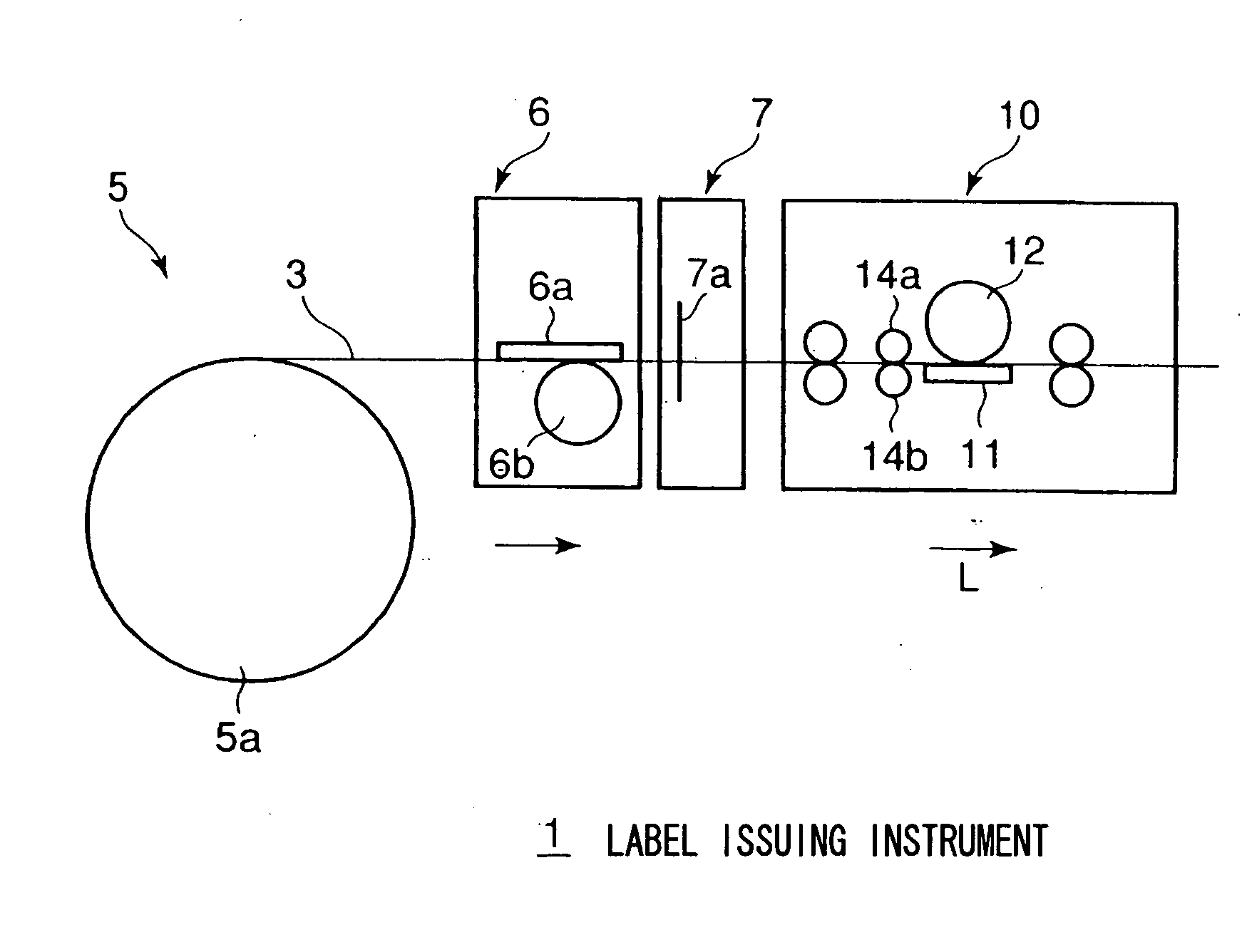
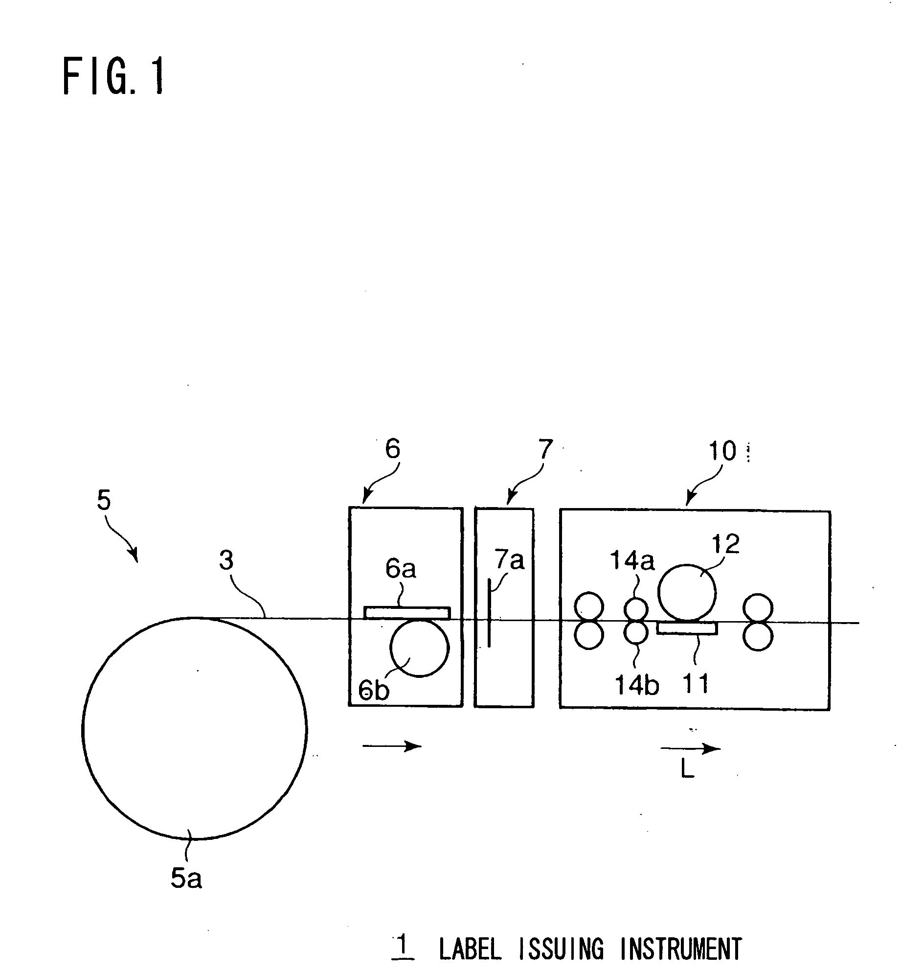
[0037] As shown in FIG. 1, in a label issuing instrument 1, a sheet supply apparatus 5 that supplies a sheet material 3, a printing apparatus 6 that prints various types of information on a thermal printing layer of the sheet material 3, a cutting apparatus 7 that cuts the sheet material 3 for which the printing has been performed by the printing apparatus 6, and a thermal activation device 10 that thermally activates a heat-sensitive adhesive layer of the sheet material 3 are arranged in the stated order along a conveyor route of the sheet material 3 in the direction indicated by an arrow L in FIG. 1.

[0038] The sheet supply apparatus 5 includes a sheet roll 5a around which the sheet ma...


PUM

PropertyMeasurementUnit
discharge speedaaaaaaaaaa
heat-sensitiveaaaaaaaaaa
holding forceaaaaaaaaaa

Abstract

Provided is a thermal activation device including a thermal activation head (11) for thermally activating a heat-sensitive adhesive layer of a sheet material (3), a platen roller (12) for holding and conveying the sheet material (3), the platen roller (12) being brought into press contact with the thermal activation head (11), and a pair of conveyor rollers (14a and 14b) that convey the sheet material (3), the conveyor rollers (14a and 14b) being provided to be located on an upstream side of the thermal activation head (11) in a conveying direction of the sheet material (3). Holding force for the sheet material (3) by the pair of conveyor rollers (14a and 14b) is made larger than holding force for the sheet material (3) by the platen roller (12) and the thermal activation head (11).

Description

BACKGROUND OF THE INVENTION [0001] 1. Field of the Invention [0002] The present invention relates to a thermal activation device for thermally activating a heat-sensitive adhesive layer of a sheet material having a printing layer formed on one surface of a sheet-like base material and the heat-sensitive adhesive layer formed on the other surface thereof. The present invention also relates to a method of conveying the sheet material. [0003] 2. Description of the Related Art [0004] For example, in a distribution center and shops, labels for displaying various types of information such as prices and for displaying barcodes for management by means of POS (point of sales) terminals have been used by being attached to articles. As this type of label, a proposal has been made of a label, which is issued using a sheet material having a printing layer formed on one surface of a sheet-like base material and a heat-sensitive adhesive layer formed on the other surface thereof. [0005] In general...

Claims


Application Information

Patent Timeline
Patent Type & Authority Applications(United States)
IPC IPC(8): B41J11/04B41J13/03B65C9/25
CPCY10T156/17B65C9/25
Inventor TAKAHASHI, MASANORIOBUCHI, TATSUYASATO, YOSHINORIHOSHINO, MINORUKOHIRA, HIROYUKI
Owner SEIKO INSTR INC
Why Eureka
Try Eureka