Shaped flow distribution in filtration cassettes

a flow distribution and filtration cassette technology, applied in the field of filtration devices, can solve the problems of incomplete cross-flow cleaning action, non-uniform flow formation, and inability to clean the filtration cassette, so as to improve the flow dynamics, and reduce or eliminate the formation of non-uniformities

Inactive Publication Date: 2005-12-08
GE HEALTHCARE BIO SCI CORP
View PDF6 Cites 11 Cited by
  • Summary
  • Abstract
  • Description
  • Claims
  • Application Information

AI Technical Summary

Benefits of technology

[0011] The present invention overcomes the deficiencies in the prior art filtration cassettes by providing a filtration cassette having shaped flowpaths to minimize, if not eliminate, the occurrence of dead spots therein. The present invention contemplates that the flowpaths may be shaped at their opposing ends or for up to their entire length between the flowports.
[0013] The present invention improves the flow dynamics about the leading edges of the sealed apertures by flowing the sealing resin so that it protrudes into the main passageway defined by the screens. Desirably, the sealing resin extends into the passageways so as to significantly reduce or eliminate the formation of non-uniformities in fluid flow therethrough. The porous mesh may define apertures shaped so as to direct the resin during vacuum drawing to a desired location in the flow channels. The sealing resin may be flowed from either the outside edge of the porous screens towards the flowpath, from the interior ports in the screen towards the interior and edges of the screen, or a combination of both. The porous mesh may further include a shaped perimetrical edge which also assists in the drawing of a flowable resin into the porous mesh to further define the flow channels so as to significantly reduce or eliminate the formation of non-uniformities in the fluid flow.
[0014] It is further contemplated by the present invention that the flowpaths may be formed by stamping shaped gaskets which may be combined with the screens so as to form shaped flowpaths which minimize or altogether prevent the formation of deadspots.

Problems solved by technology

One deficiency in many filtration devices, including cassette filters, is the creation of ‘dead spots’ or other flow non-uniformities. FIG. 3 depicts the fluid flow through a multi-apertured feed / retentate screen 50.
Non-uniform flow can create several problems for utilization of the filter, including accumulation of filtered debris in the areas of low shear resulting in, e.g., incomplete cross-flow cleaning action.
This accumulation in turn creates problems cleaning the filtration cassette between uses as low shear areas are not evenly exposed to cleaning action.
This phenomenon results in incomplete utilization of the membrane area as well as contamination from one use to the next due to the poor cleaning.
Such entrapped material would be lost to the user.
It has been seen that the most pronounced problems occur within the feed layer, including areas adjacent the corners of the layers as well as near the seals of manifold holes corresponding to the filtrate distribution.

Method used


Image

  • Shaped flow distribution in filtration cassettes
  • Shaped flow distribution in filtration cassettes
  • Shaped flow distribution in filtration cassettes

Examples


Embodiment Construction

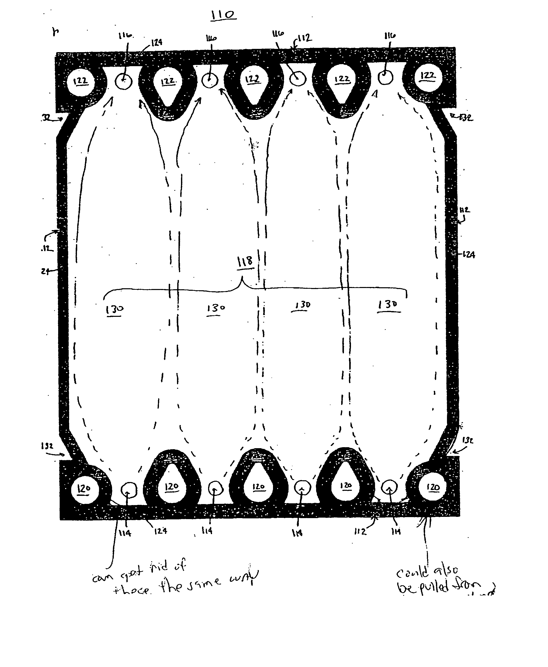
[0041]FIG. 5 depicts an elongate porous feed / retentate screen 110 of the present invention and is desirably be incorporated into a filtration cassette between opposing filter membranes or between a filter membrane and an impervious film. Screen 110 is desirably formed of a suitable material for filtration applications and is typically formed from a polymeric or metal mesh which permits fluid flow across its length. Screen 110 includes a perimetrical edge 112 and defines a plurality of longitudinally-opposed first and second filtrate apertures 114 and 116 as is known in the art. Screen 110 defines an elongate filtrate passageway 118 extending between first and second filtrate apertures 114 and 116. Filtrate apertures 114 and 116 are shown as being circular in shape. Screen 110 also defines a plurality of longitudinally-opposed feed / retentate apertures 120 and 122. Perimetrical seal 124 bounds passageway 118. Feed / retentate apertures 120 and 122 are bound by aperture seals 126 which e...


PUM

PropertyMeasurementUnit
shapeaaaaaaaaaa
mechanical integrityaaaaaaaaaa
perimeteraaaaaaaaaa

Abstract

The present invention improves the flow dynamics about the leading edges of the sealed apertures within a filtration cassette by flowing a sealing resin so that it protrudes into the main passageway defined by the porous screens thereof. The sealing resin defines at least an end portion of a fluid channel in each passageway. Desirably, the sealing resin extends into the passageway so as to significantly reduce or eliminate the formation of he non-uniformities in fluid flow therethrough. The porous mesh may define apertures shaped so as to direct the resin during vacuum drawing to a desired location in the flow channels. The porous mesh may further include a shaped perimetrical edge which also assists in the drawing of a flowable resin into the porous mesh to further define the flow channels so as to significantly reduce or eliminate the formation on non-uniformities in the fluid flow.

Description

FIELD OF THE INVENTION [0001] The present invention relates generally to the field of filtration devices. More specifically, the present invention relates to a filtration cassette having shaped flow distribution. BACKGROUND OF THE INVENTION [0002] Cassette filtration devices have become the standard in many high technology filter applications such as in biopharmaceutical processing, virus removal from blood products, as well as water purification. Cassette filters are well known in the art and typically include a number of filter elements selectively bound together with a flowable resin so as to define internal channels for the distribution of feed, filtrate, and retentate streams therethrough. Typically, the channels are polymer based screens or plates with the appropriate openings that serve to space the filter elements from each other. The use of polymer screens in the formation of distribution layers provides a high degree of flow uniformity as well as good control of the shear ...

Claims


Application Information

Patent Timeline
Patent Type & Authority Applications(United States)
IPC IPC(8): B01D63/08
CPCB01D63/084B01D63/081
Inventor HERCZEG, ATTILA
Owner GE HEALTHCARE BIO SCI CORP
Why Eureka
Try Eureka