High-reliability electro-mechanical actuator

a high-reliability, electro-mechanical actuator technology, applied in the direction of lifting equipment, gearing, transportation and packaging, etc., can solve the problems of increasing design complexity, adding weight, and requiring a lot of ply to distribute and control the pressurized working fluid

Active Publication Date: 2005-12-08
THE BOEING CO
View PDF11 Cites 77 Cited by
  • Summary
  • Abstract
  • Description
  • Claims
  • Application Information

AI Technical Summary

Benefits of technology

[0007] A fault-tolerant, electrically-powered actuator uses two or more, independent integrated motor modules in the same housing to drive an output ram that can be extended from and retracted into a housing that encloses the electric motor module that drive the ram into and out of the housing. The integrated motor module (FIG. 2) is defined as a unit that consist of one or more electric motor armature / field unit that provide the driving function for an engaged or active roller scres nut assembly. The roller screw nut assembly (FIG. 2A) consists of helical threaded rollers, nut assembly directly coupled to a common screw shaft. The ram's outside surface is threaded. Since the output ram is threaded, the ram can moved into or out of the housing by the rotation of one or more “drive nuts” that engage the threads of the output ram and which are rotated themselves but laterally fixed in place such that the output ram moves laterally on the rotation of the drive nut.

Problems solved by technology

A problem with hydraulic actuators is the plumbing required to distribute and control the pressurized working fluid.
In an airplane, a pump that generates high-pressure working fluid and the plumbing required to route the working fluid add weight and increase design complexity because the hydraulic lines must be carefully routed.
Electric actuators, which are powered and controlled by electric energy, require only wires to operate and control but a problem with prior art electrical actuators is their reliability.
Windings of electrical motors are susceptible to damage from heat and water.
Bearings on motor shafts wear out.
The transmission between the motor and the load, and which is inherently more complex than the piston and cylinder used in a hydraulic actuator, is also susceptible to failure.

Method used


Image

  • High-reliability electro-mechanical actuator
  • High-reliability electro-mechanical actuator
  • High-reliability electro-mechanical actuator

Examples


Embodiment Construction

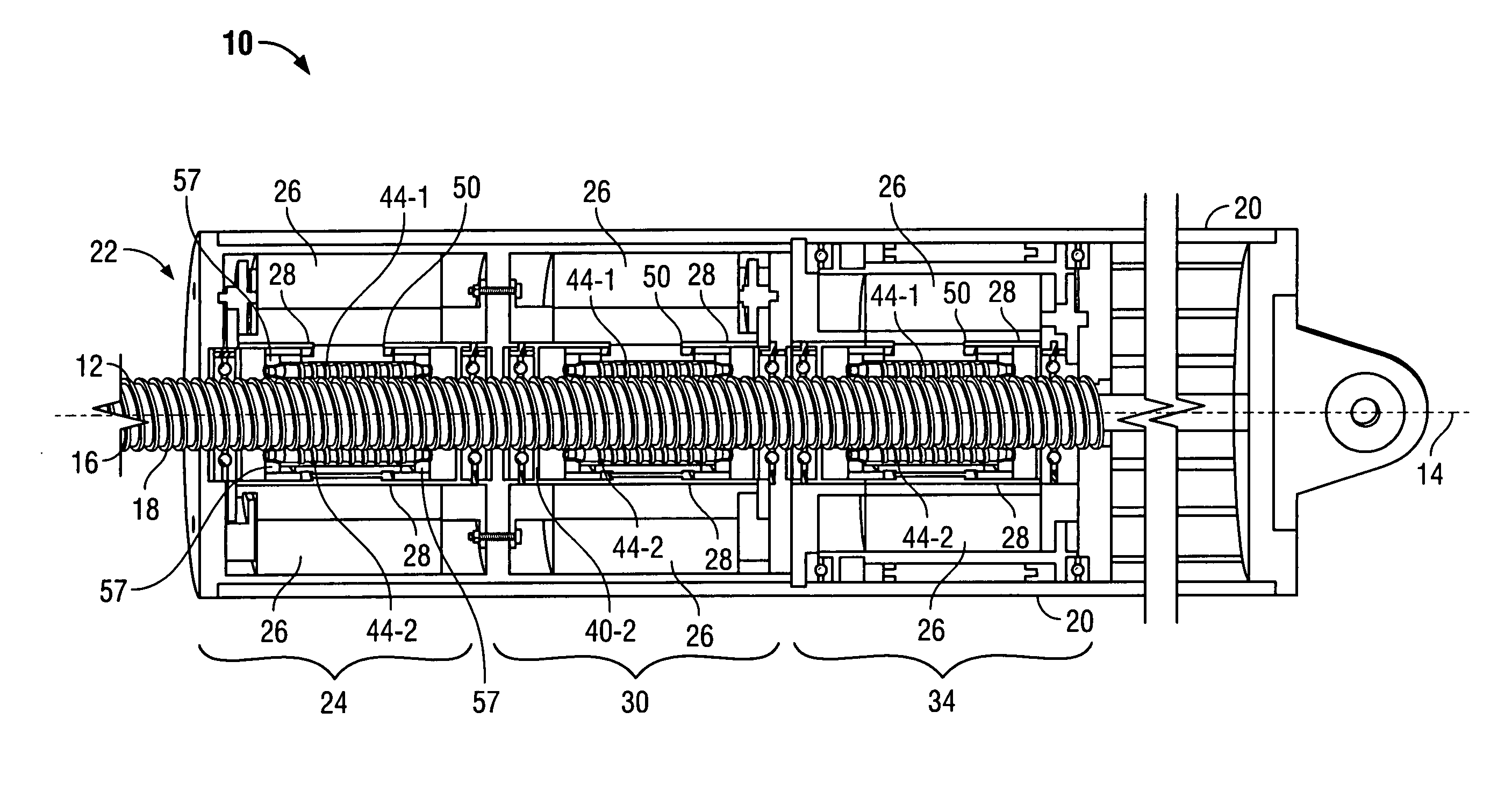
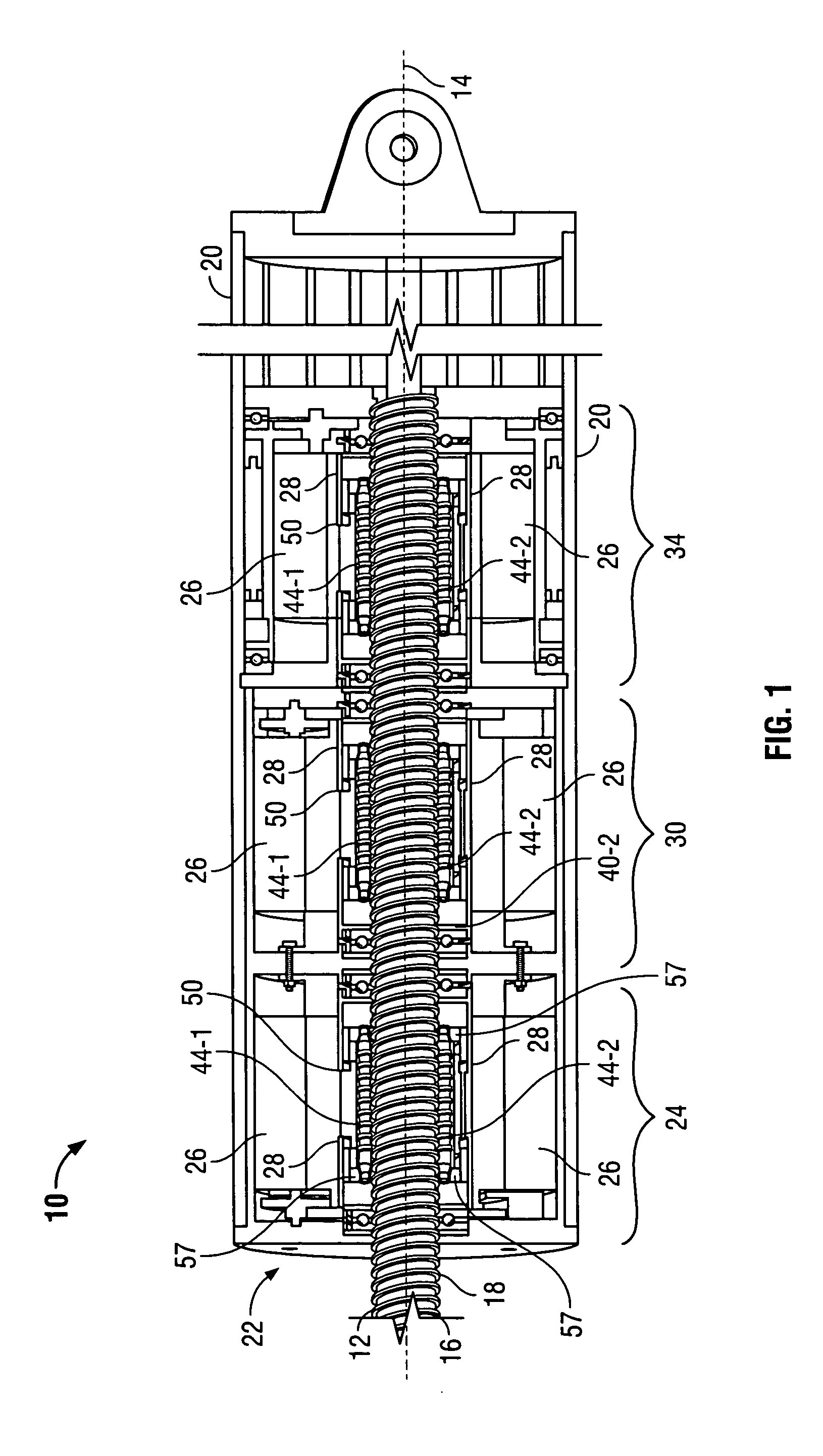
[0018]FIG. 1 is a cross-sectional view of a preferred embodiment of an electrically-powered and fault tolerant electrical actuator 10.

[0019] Briefly, the actuator 10, is comprised of cylindrically-shaped housing 20 that encloses two or more integrated electrical motor modules (three shown) 24, 30 and 34 that can drive an output ram 12, the exterior surface 16 of which is helically threaded. A helical thread 18 (also referred to as “threads”) on the output ram 12 surface are threaded into one or more complementary “drive nuts” within the housing that engage the threaded output ram 12 and which can rotate about the output ram 12 but which are laterally fixed in the housing, i.e., they cannot move along the length of the output ram 12. When the end of the output ram (not shown in FIG. 1) is connected to a machine, such as an aircraft's control surface, lateral movement motion of the ram 12 operates or controls the machine to which the output ram 12 is coupled.

[0020] The output ram 12...


PUM


Abstract

An electrical actuator comprises two or more electrical motors to drive a threaded screw ram. Each motor has an armature that drives a threaded roller screw that is engaged to the threaded screw ram. Each armature of each motor is independently engageable and/or dis-engageable with the ram. The motor armatures are engageable and disengageable by way of threaded roller screws, the ends of which are tapered to enable them to be lifted away from or lowered into engagement with the threaded ram.

Description

BACKGROUND OF THE INVENTION [0001] This invention relates to actuators. An “actuator” is defined in the Merriam-Webster's Collegiate Dictionary, Tenth Edition as a mechanical device for moving or controlling something. Actuators perform myriad functions and enable many modern conveniences. [0002] Aircraft for example, require actuators to fly. Flaps, spoilers and ailerons in each wing, each require an actuator. Actuators in the tail control the rudder and elevators. Actuators in the fuselage open and close the doors that cover the landing gear bays. Actuators raise and lower the landing gear. Actuators on each engine control thrust reversers by which the plane is decelarated. [0003] In addition to uses in aircraft, actuators are used in computer disk drives to control the location of the read / write head by which data is stored on and read from the disk. Actuators are used in robots, i.e., in automated factories to assemble products. Actuators operate brakes on vehicles; open and clo...

Claims


Application Information

Patent Timeline
Patent Type & Authority Applications(United States)
IPC IPC(8): B64C13/00B64C13/24F16H25/20F16H27/02H02K7/06H02K16/00H02K19/38H02K41/00
CPCB64C13/00B64C13/24F16H25/2015F16H25/2025F16H25/2266F16H2025/2071Y10T74/18664H02K7/06H02K16/00Y02T50/44Y10T74/19767Y10T74/186F16H2025/2078Y02T50/40
Inventor BLANDING, DAVID E.WATANABE, ATSUO J.
Owner THE BOEING CO
Why Eureka
Try Eureka