Micro-electromechanical system (MEMS) based current & magnetic field sensor having capacitive sense components

a micro-electromechanical system and sensor technology, applied in the direction of voltage/current isolation, base element modification, instruments, etc., can solve the problems of reducing the efficiency of current sensors, affecting the accuracy of sensors, and affecting the use of sensors in smaller scale environments

Active Publication Date: 2005-12-08
ABB SPA
View PDF8 Cites 74 Cited by
  • Summary
  • Abstract
  • Description
  • Claims
  • Application Information

AI Technical Summary

Problems solved by technology

However, there are several disadvantages associated with existing current sensors that use magnetic fields to measure electrical current in high voltage applications.
This current flow induces heating, which reduces the efficiency of the current sensors and introduces a possible error factor in sensor accuracy.
Since existing current sensors are large and bulky, their physical and electrical operating characteristics have up to now prevented their use in smaller scale environments.

Method used


Image

  • Micro-electromechanical system (MEMS) based current & magnetic field sensor having capacitive sense components
  • Micro-electromechanical system (MEMS) based current & magnetic field sensor having capacitive sense components
  • Micro-electromechanical system (MEMS) based current & magnetic field sensor having capacitive sense components

Examples


Embodiment Construction

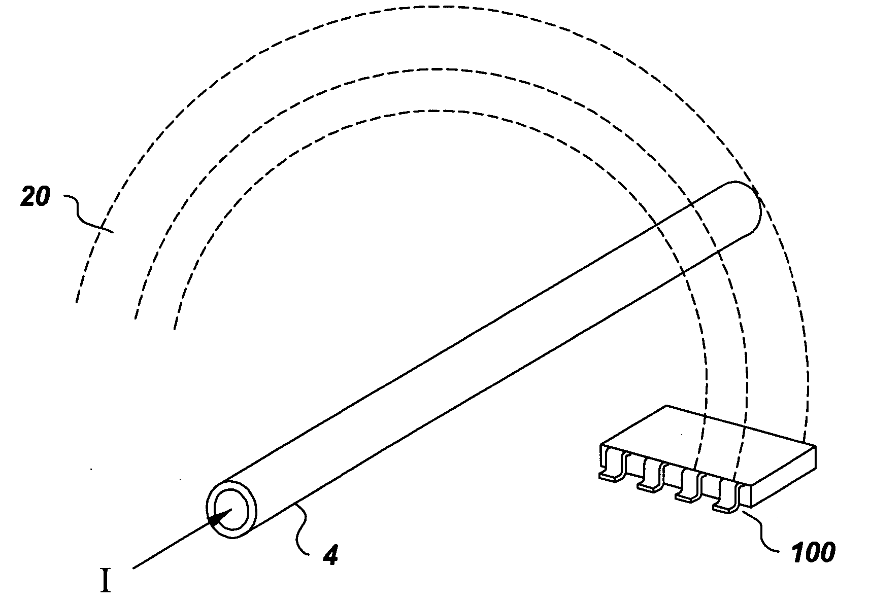
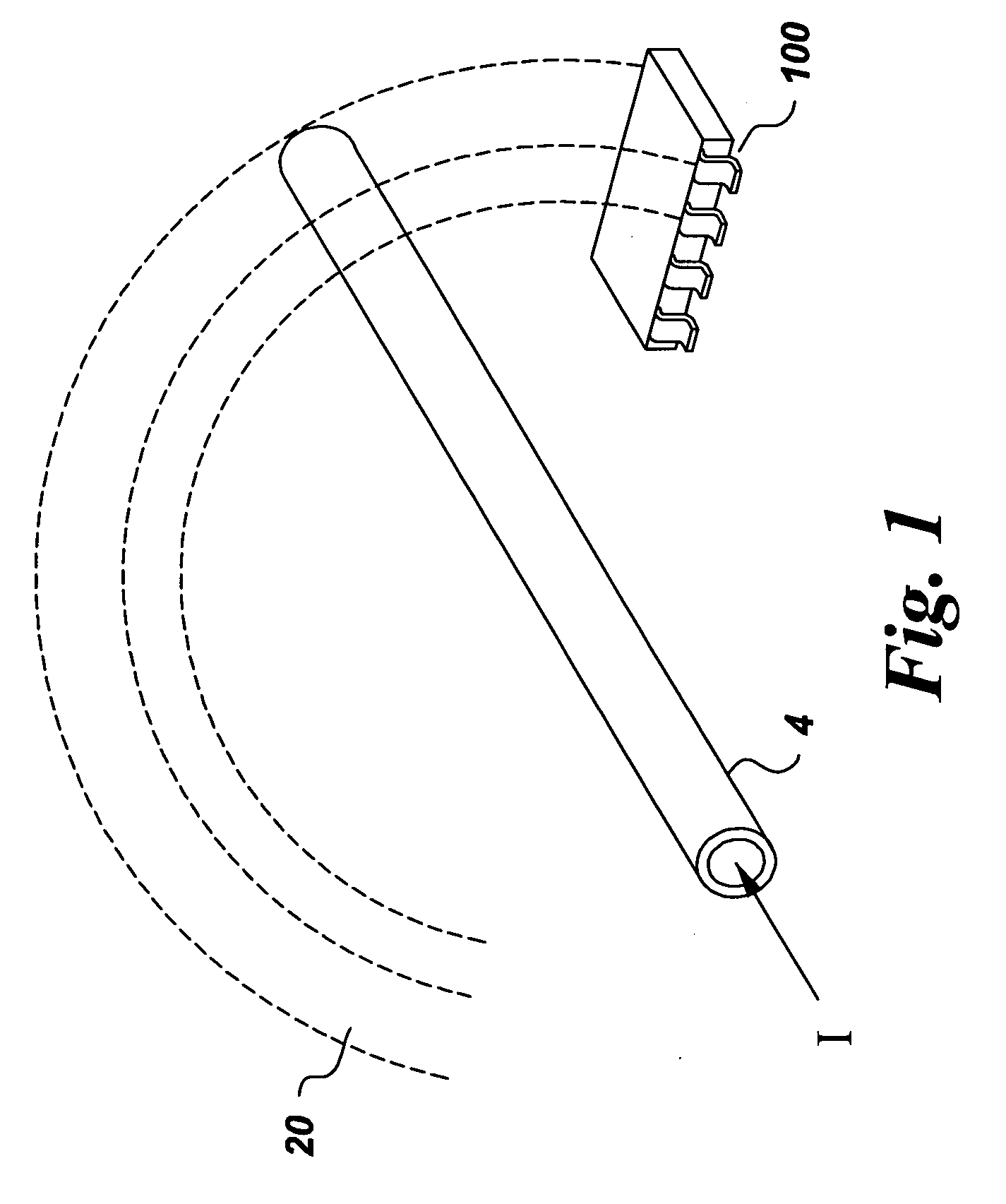
[0018]FIG. 1 illustrates one embodiment of a MEMS current and magnetic field sensing device described herein and hereinafter generally referred to as “current sensor 100”. As shown, conductor 4 carrying a current I generates a magnetic field 20. In accordance with one embodiment of the present disclosure, current sensor 100 can be used to sense the current I in a current carrying conductor 4, without having to make physical contact with the current carrying conductor. In accordance with the illustrated embodiment, the MEMS-based current sensor 100 operates to sense and determine the current I carried by the conductor 4 by making use of the Lorentz force resulting when current sensor 100 is positioned in the magnetic field 20 generated by current I. In one embodiment, the current sensor 100 includes a magnetic field sensing component having a capacitive magneto-MEMS component for sensing magnetic fields and for providing, in response thereto, an indication of the current present in t...


PUM


Abstract

A micro-electromechanical system (MEMS) based current & magnetic field sensor includes a MEMS-based magnetic field sensing component having a capacitive magneto-MEMS component, a compensator and an output component for sensing magnetic fields and for providing, in response thereto, an indication of the current present in a respective conductor to be measured. In one embodiment, first and second mechanical sense components are electrically conductive and operate to sense a change in a capacitance between the mechanical sense components in response to a mechanical indicator from a magnetic-to-mechanical converter.

Description

RELATED APPLICATIONS [0001] This application is a continuation-in-part of U.S. patent application Ser. No. 10 / 863,442 entitled “MEMS BASED CURRENT SENSOR USING MAGNETIC-TO-MECHANICAL CONVERSION AND REFERENCE COMPONENTS”, which is hereby fully incorporated by reference.BACKGROUND [0002] The present disclosure relates generally to electrical current and magnetic field sensing devices. More particularly, the present disclosure relates to a micro-electromechanical system (MEMS) based current and magnetic field sensor. [0003] It is known that a current carrying conductor produces a magnetic field in the vicinity of the current carrying conductor. It is also known that the magnetic field produced by the current carrying conductor can induce a force with another current carrying conductor disposed in the magnetic field produced by that current carrying conductor. As such, one approach used to sense electrical current involves the use of a sensor that measures the magnetic field induced by ...

Claims


Application Information

Patent Timeline
Patent Type & Authority Applications(United States)
IPC IPC(8): G01R15/20G01R33/028
CPCG01R33/0283G01R15/148G01R33/0286
Inventor ZRIBI, ANISCLAYDON, GLENN SCOTTKAPUSTA, CHRISTOPHER JAMESMEYER, LAURA JEANBERKCAN, ERTUGRULTIAN, WEI-CHENG
Owner ABB SPA
Why Eureka
Try Eureka