Electronic device

a technology of electronic devices and power consumption, applied in the field of electronic devices, can solve problems such as the disadvantage of power consumption, and achieve the effect of reducing the cost of useless power consumption

Inactive Publication Date: 2005-12-08
SONY ERICSSON MOBILE COMM JAPAN INC
View PDF10 Cites 51 Cited by
  • Summary
  • Abstract
  • Description
  • Claims
  • Application Information

AI Technical Summary

Benefits of technology

[0013] According to the present invention, because the power supplied to the active element can be control

Problems solved by technology

However, because the passive elements of a contact type in which electrodes are slidably contacted have a problem of chattering, endurance and the like, there is proposed one using an active element of a non-contact type such as a Hall element to detect the rotation of jog dial (refer to, for example, Patent Reference 2: Ja

Method used


Image

  • Electronic device
  • Electronic device
  • Electronic device

Examples


Embodiment Construction

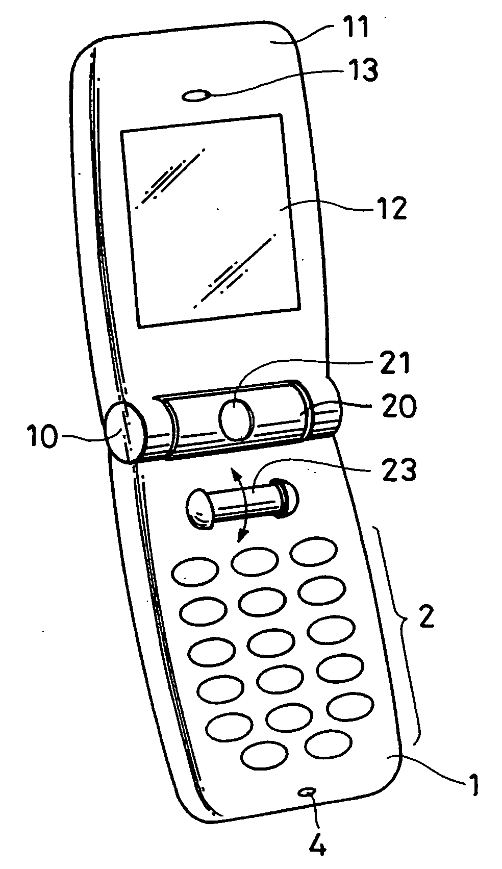
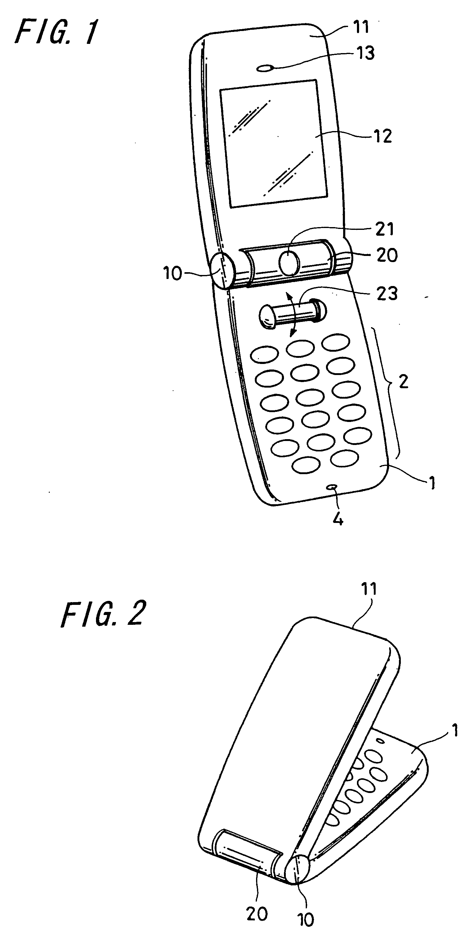
[0029] Hereinafter, an embodiment of the electronic device according to the present invention when applied to a mobile phone unit will be described with reference to FIGS. 1 through 9. In this embodiment, the invention is applied to what is called a folding-type mobile phone unit whose casing can be folded. FIG. 1 shows a perspective view showing an outer appearance of the folding-type mobile phone unit according to this embodiment when a lower casing and an upper casing are in a fully opened state.

[0030] In FIG. 1, a numeral 1 denotes a lower casing and a numeral 11 denotes an upper casing; the lower casing 1 is joined with the upper casing 11 through a hinge portion 10 to be freely opened and closed; inside the lower casing 1 (on the surface opposing the upper casing 11 in a closed state) are provided a group of operating buttons 2 including a power-supply button, a key-lock button or the like, what is called a jog dial 23 having both a rotation-detecting function and an orthogon...


PUM


Abstract

The object of the present invention is to provide an electronic device capable of reducing consumption of power supplied to active elements used for a rotary operation unit in a stand-by time.
The electronic device according to the present invention includes the rotary operation unit that is freely rotatable, active elements 31 and 32 for detecting rotation of the rotary operation unit, and control means 43 for controlling the power supply to the active elements 31 and 32 depending on a state of the device.

Description

TECHNICAL FIELD [0001] The present invention relates to an electronic device suitable to be applied to a mobile telephone unit, PDA (personal digital assistant) or the like including rotary operation means. BACKGROUND ART [0002] Conventionally, what is called a jog dial has been developed as rotary operation means which can be incorporated in an electronic device such as a mobile phone unit. A mechanism of detecting rotation of the jog dial includes a rotary disc and a fixed disc laminated almost in parallel therewith to form a rotary encoder. Further, for example, a set of opposed electrodes arranged on the rotary disc are slidably contacted with several sets of opposed electrodes arranged on the fixed disc, each of the electrodes being slightly shifted in a circumferential direction, and when the rotary disc is rotated, pulse signals having a phase difference depending on the direction of rotation are obtained to detect the rotation (refer to, for example, Patent Reference 1: Japa...

Claims


Application Information

Patent Timeline
IPC IPC(8): H04M1/73G06F3/033G06F1/26H04M1/23H04M1/00H04M1/247G06F1/32
CPCG06F1/3203G06F1/3259G06F1/3265G06F3/0362Y02D70/00H04M1/233H04W52/0251Y02D10/153Y02D10/155H04M1/23Y02D10/00Y02D30/70H04B1/40
Inventor OKAMOTO, ICHIRO
Owner SONY ERICSSON MOBILE COMM JAPAN INC
Why Eureka
Try Eureka