Plasma display panel

A display panel and plasma technology, applied in the direction of alternating current plasma display panels, gas discharge electrodes, solid cathode parts, etc., can solve the problems of shortening the life of the plasma display panel 10, and improve luminous efficiency and light emission efficiency, reduce Capacitance, effect of size increase

Inactive Publication Date: 2006-08-09
SAMSUNG SDI CO LTD
View PDF1 Cites 2 Cited by
  • Summary
  • Abstract
  • Description
  • Claims
  • Application Information

AI Technical Summary

Problems solved by technology

This will shorten the life of the plasma display panel 10

Method used


Image

  • Plasma display panel
  • Plasma display panel
  • Plasma display panel

Examples


Embodiment Construction

[0046] Hereinafter, embodiments of the present invention will be more fully described in conjunction with the accompanying drawings.

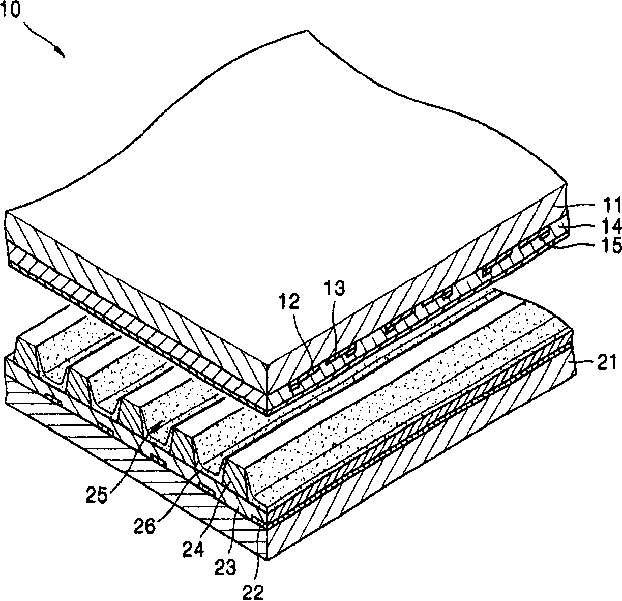
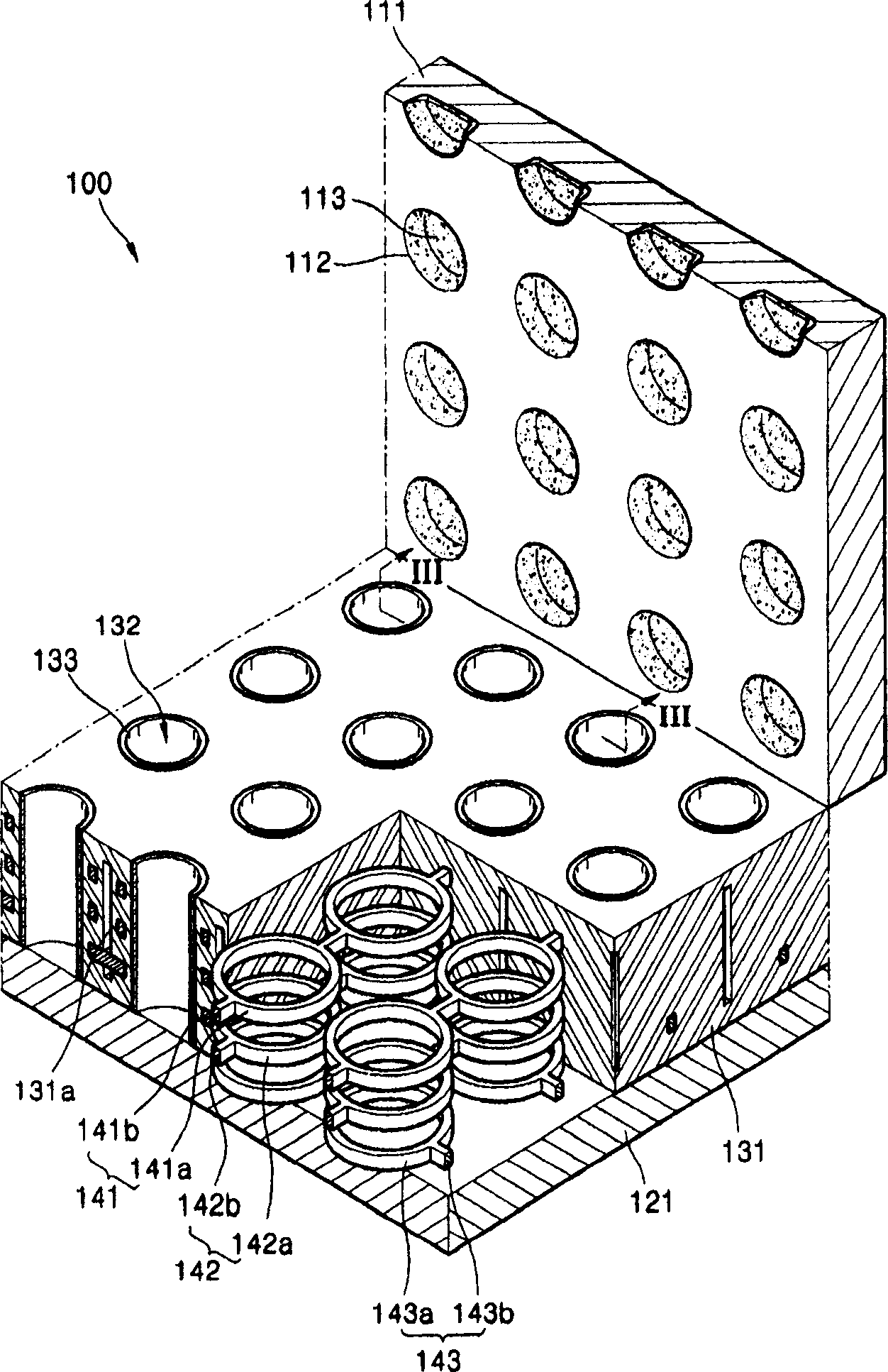
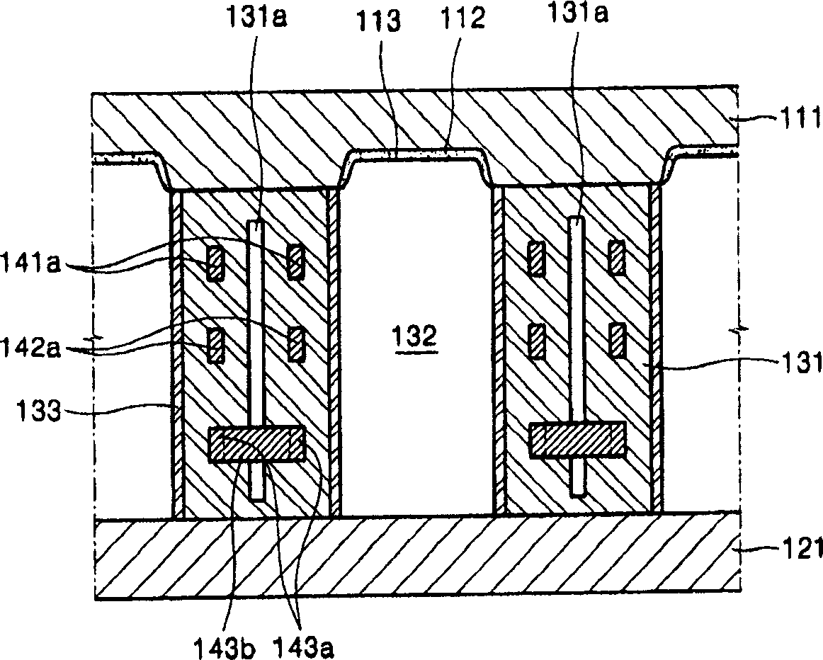
[0047] see figure 2 and image 3 A plasma display panel (PDP) 100 according to one embodiment of the present invention includes an upper substrate 111 and a lower substrate 121 opposite to the upper substrate 111 . An image is displayed onto at least one of the upper substrate 111 and the lower substrate 121 . The substrate on which the image is displayed is made of light-transmissive material.

[0048]The barrier structure 131 is disposed between the upper substrate 111 and the lower substrate 121 . The barrier structure 131 separates a plurality of discharge cells 132 corresponding to sub-pixels and prevents undesired discharge from being generated due to crosstalk between the discharge cells 132 and the like. In one embodiment, the barrier structure 131 may be designed such that the discharge cells 132 have a closed structure. In one em...


PUM


Abstract

A plasma display panel (PDP) including a plurality of cavities within a barrier structure is disclosed. In one embodiment, the PDP includes i) an upper substrate, ii) a lower substrate facing the upper substrate, iii) the barrier structure disposed between the upper substrate and the lower substrate and defining discharge cells, iv) upper discharge electrodes arranged at intervals within the barrier structure and each surrounding at least parts of the discharge cells, v) lower discharge electrodes arranged at intervals within the barrier structure, located under the upper discharge electrode, and each surrounding at least parts of the discharge cells, and vi) phosphor layers disposed over the discharge cells. According to one embodiment of the present invention, ineffective power consumption can be reduced and heat generated in the discharge cells can be effectively dissipated.

Description

[0001] Cross References to Related Patent Applications [0002] This application claims the benefit of Korean Patent Application No. 10-2005-0009724 filed in the Korean Intellectual Property Office on February 2, 2005, the disclosure of which is hereby incorporated by reference in its entirety. technical field [0003] The present invention relates to a plasma display panel capable of reducing waste power consumption and improving heat discharge. Background technique [0004] A plasma display panel (PDP) device can provide a large screen size and excellent performance, such as high-quality image display, very thin and light design, and a large viewing angle. Since a method of manufacturing a plasma display panel is simpler and easier to increase in size compared to methods of manufacturing other flat panel displays, the plasma display panel has drawn attention and is expected to be the most promising next-generation flat panel display. [0005] The plasma display panels are...

Claims


Application Information

Patent Timeline
Patent Type & Authority Applications(China)
IPC IPC(8): H01J17/49H01J17/04H01J17/16H01J11/10H01J11/16H01J11/22H01J11/32H01J11/34H01J11/36H01J11/40H01J11/42
CPCH01J2211/363H01J11/16H01J11/36H01J11/22
Inventor 柳宪锡李源周
Owner SAMSUNG SDI CO LTD
Why Eureka
Try Eureka