
Pure electric driving system for loader and loader

A pure electric drive and drive system technology, used in mechanically driven excavators/dredgers, earthmovers/shovels, construction, etc., can solve problems such as increasing fuel consumption, aggravating the environment, and pollution hazards

Pending Publication Date: 2021-05-18
TOP GEAR POWERTRAIN TECH CO LTD
View PDF0 Cites 2 Cited by
  • Summary
  • Abstract
  • Description
  • Claims
  • Application Information

AI Technical Summary

Problems solved by technology

However, the traditional loader driven by a fuel engine now has only a single drive unit, the engine. Under different operating conditions, it is impossible to accurately allocate energy and power to each device according to the action requirements of each mechanism, which greatly increases the load. Useless power consumption, increased fuel consumption
[0003] In addition, because the driving principle of the fuel loader is to drive the machine through the combustion of fuel in the engine to generate power, and the incomplete combustion of fuel will produce pollutants such as carbon dioxide, which will aggravate the pollution hazards to the environment

Method used


Image

  • Pure electric driving system for loader and loader
  • Pure electric driving system for loader and loader
  • Pure electric driving system for loader and loader

Examples


Embodiment Construction

[0025] The present disclosure will be further described in detail below with reference to the drawings and embodiments. It can be understood that the specific implementation manners described here are only used to explain relevant content, rather than to limit the present disclosure. It should also be noted that, for ease of description, only parts related to the present disclosure are shown in the drawings.

[0026] It should be noted that, in the case of no conflict, the implementation modes and the features in the implementation modes in the present disclosure can be combined with each other. The present disclosure will be described in detail below with reference to the drawings and embodiments.

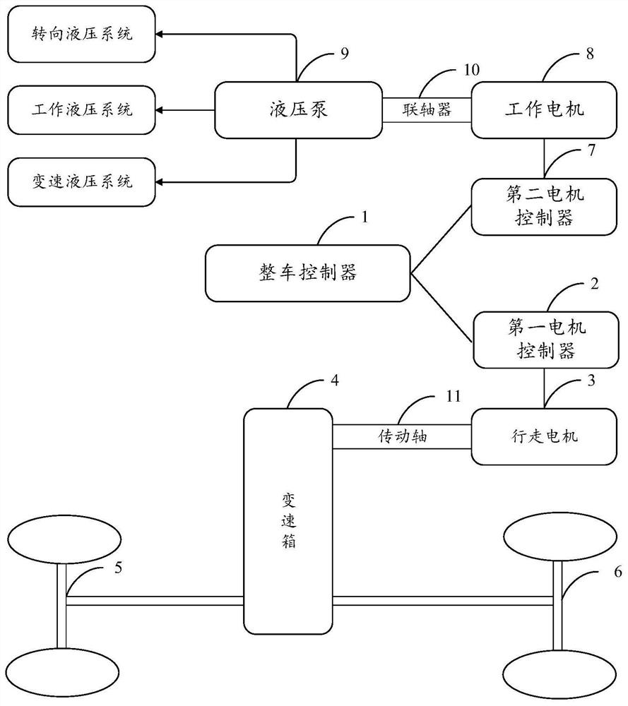
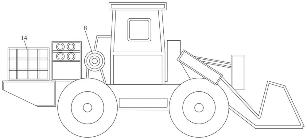
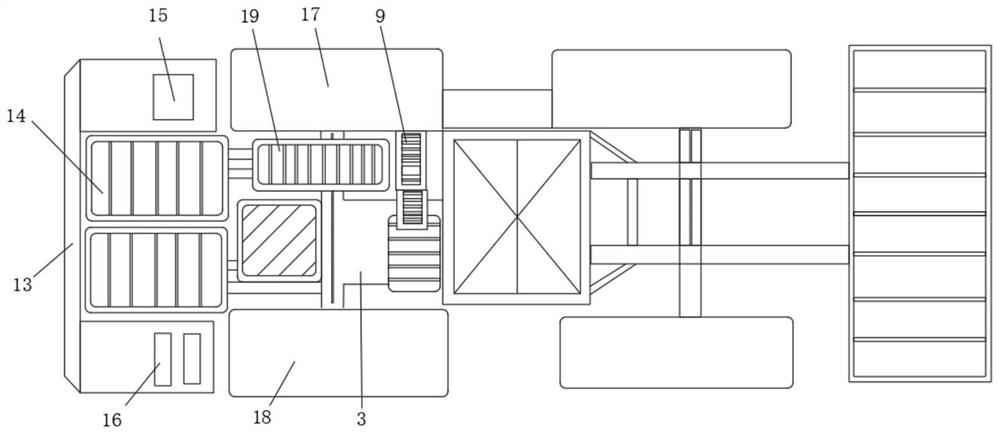
[0027] see figure 1 , loader pure electric drive system, including travel motor drive system, working motor drive system and vehicle controller 1;

[0028] The travel motor drive system includes a first motor controller 2, the first motor controller 2 is connected to the travel...


PUM


Abstract

The invention provides a pure electric driving system for a loader and the loader. The pure electric driving system for the loader comprises a walking motor driving system, a working motor driving system and a whole vehicle controller; the walking motor driving system comprises a first motor controller, the first motor controller is connected with a walking motor, the walking motor is connected with a gearbox, and the gearbox is connected with a front axle and / or a rear axle of the loader; and the working motor driving system comprises a second motor controller, the second motor controller is connected with a working motor, the working motor is connected with a hydraulic pump, and the hydraulic pump is connected with the loader. According to the pure electric driving system for the loader and the loader, the walking function and the working function of the loader are relatively independent, power distribution is facilitated, energy consumption is reduced, and energy is saved.

Description

technical field [0001] The present disclosure relates to the technical field of engineering machinery, in particular to a loader pure electric drive system and the loader. Background technique [0002] Since the walking function and operation function of the loader and some construction machinery are relatively separated, in order to obtain optimized operation performance and minimize energy consumption, it is necessary to allocate appropriate power and energy to different operation conditions and different operation actions. However, the traditional loader driven by a fuel engine now has only a single drive unit, the engine. Under different operating conditions, it is impossible to accurately allocate energy and power to each device according to the action requirements of each mechanism, which greatly increases the load. Useless power consumption increases fuel consumption. [0003] In addition, because the driving principle of the fuel loader is to drive the machine throu...

Claims


Application Information

Patent Timeline
Patent Type & Authority Applications(China)
IPC IPC(8): E02F3/28E02F3/36E02F3/42E02F9/20E02F9/22
CPCE02F3/28E02F3/36E02F3/42E02F9/2058E02F9/22E02F9/2079E02F9/2253E02F9/2292
Inventor 李杉邓跃跃陆海峰魏毅赵向阳
Owner TOP GEAR POWERTRAIN TECH CO LTD
Learn More