Cylindrical heat pipe structure

a technology of cylindrical pipes and heat pipes, applied in the direction of indirect heat exchangers, lighting and heating apparatus, stationary conduit assemblies, etc., can solve the problems of not meeting the heat dissipation rate, no longer supporting the heat dissipation capacity of the central processing unit, and generating a large amount of heat, so as to increase the condensation performance, increase the condensation area, and enhance the liquid transfer speed of the wick structure

Inactive Publication Date: 2005-12-15
AUGUX CO LTD
View PDF8 Cites 16 Cited by
  • Summary
  • Abstract
  • Description
  • Claims
  • Application Information

AI Technical Summary

Benefits of technology

[0009] The present invention is to provide a cylindrical heat pipe structure, the wick structure of which is firmly attached to the inner surface of the heat pipe so as to enhance the liquid transfer speed of the wick structure.
[0010] Furthermore, the present invention is to provide a cylindrical heat pipe structure, wherein the area of the condensation end in the heat pipe is increased, for rapidly condensing the hot air generated from the heat exchange with the heat source into liquid.
[0011] One feature of the present invention is in that the heat pipe includes a hollow pipe body. The pipe body contains a working fluid. A plurality of trenches is formed on the inner surface of the pipe body. The heat pipe further includes a plurality of rib pillars, which are powder sintered to the inner surface of the pipe body. The rib pillars extend from the inner surface of the pipe body toward the center of the pipe body. A porous wick structure is formed on the surface of the rib pillars. In this manner, the rib pillars are firmly sintered on the pipe body due to the presence of the trenches. The presence of trenches also increase the condensation area, thereby increasing the condensation performance. The hot air generated by heat exchanging with the heat source is thus more rapidly condensed into liquid. The condensed liquid also rapidly moves to the porous rib pillar and transfer to the bottom portion of the pipe body for subsequent heat exchange.
[0012] Another feature of the present invention is in that the trenches are radially formed on the inner surface of the pipe body, while a plurality of rib pillars having wick structure is axially erected upright in the pipe body. The trenches effectively guide the condensed liquid to the rib pillars, while the hot air generated by heat exchange is also upwardly diffused between the rib pillars.

Problems solved by technology

However, the faster a central processing unit runs, the greater amount of heat is generated.
Conventional heat dissipation apparatus, which is composed of an aluminum extruded heat dissipater and a heat dissipation fan, may no longer support sufficient heat dissipation capacity for the central processing unit.
Thus, the heat dissipation rate is not satisfied.
Therefore, the heat dissipation rate is again not satisfied.

Method used


Image

  • Cylindrical heat pipe structure
  • Cylindrical heat pipe structure
  • Cylindrical heat pipe structure

Examples


Embodiment Construction

[0021] Reference will now be made in detail to the preferred embodiments of the present invention, examples of which are illustrated in the accompanying drawings. Wherever possible, the same reference numbers are used in the drawings and the description to refer to the same or like parts.

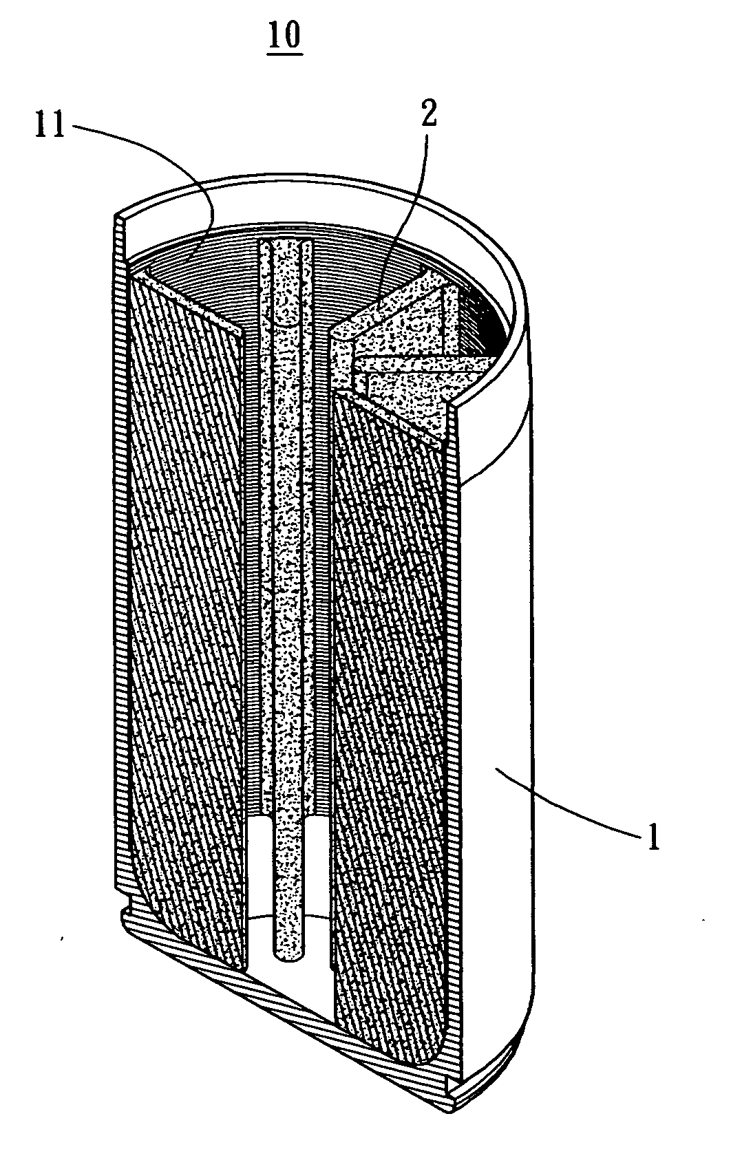
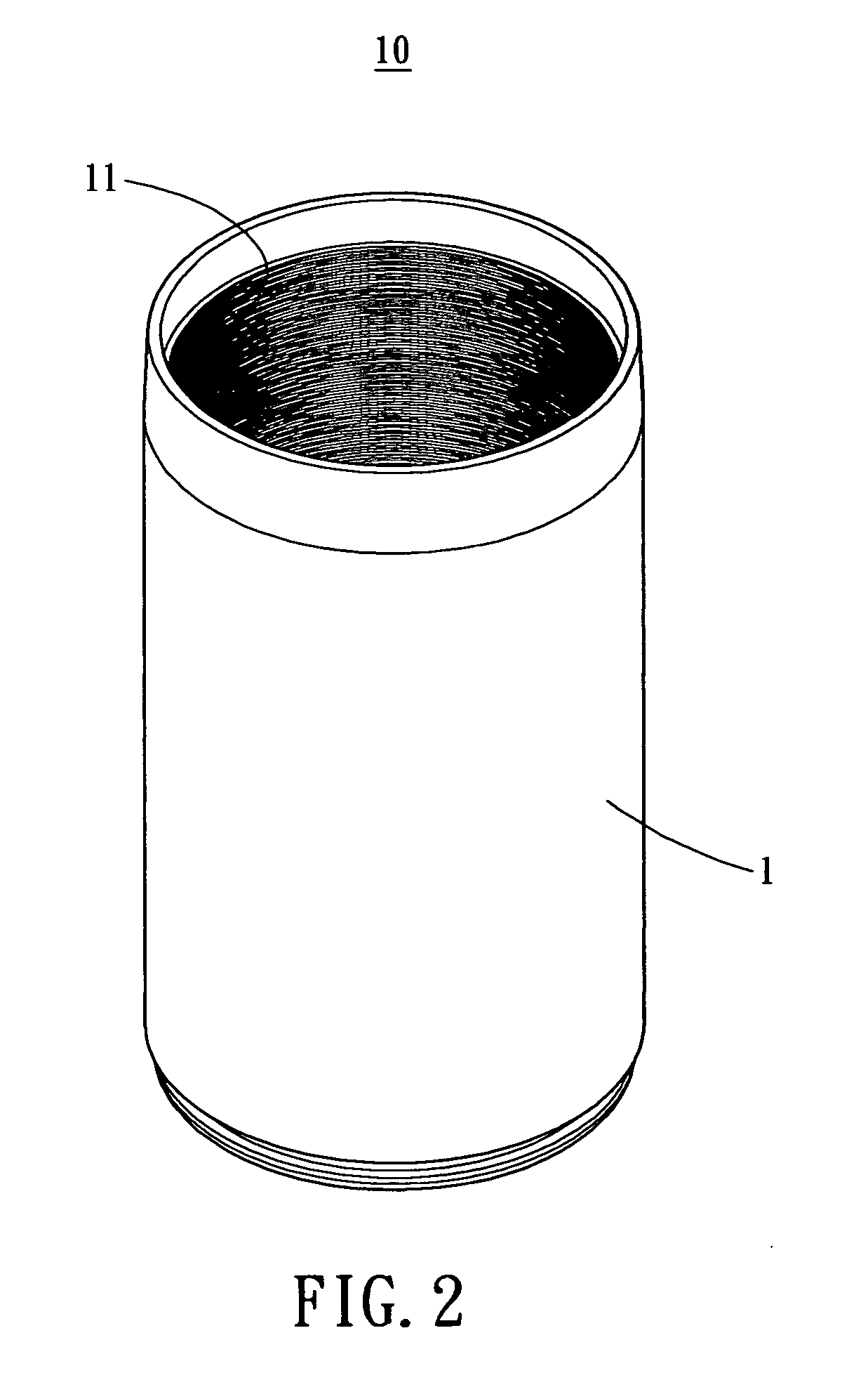
[0022] Referring to FIG. 2, a cylindrical heat pipe structure of the present invention is illustrated. The heat pipe 10 of the present invention is applicable to a heat generating device such as a central process unit, so as to dissipate heat on the heat generating device by means of heat exchange. The heat pipe 10 includes a hollow pipe body 1. In this particular embodiment, the hollow pipe body 1 is a cylindrical pipe body 1. A working fluid is contained in the hollow pipe body 1. A plurality of trenches 11 is formed on the inner surface of the pipe body 1. The trenches 11 are radially formed on the inner surface of the pipe body 1 (as illustrated in FIG. 7).

[0023] Referring to FIG. 3, FIG. 4 an...


PUM


Abstract

A cylindrical heat pipe structure includes a hollow pipe body. A working fluid is contained in the pipe body. Several trenches are formed on the inner surface of the pipe body. The cylindrical heat pipe structure further includes several rib pillars, which are powder sintered on the inner surface of the pipe body. The rib pillars are extended from the inner surface of the pipe body toward the center of the pipe body. A porous wick structure is formed on the surface of said rib pillars. The rib pillars are firmly sintered on the pipe body due to the presence of the trenches. The presence of trenches may also increase the condensation area, thereby increasing the condensation performance. The hot air generated by heat exchanging with the heat source may thus more rapidly be condensed into liquid. The condensed liquid may also rapidly move to the porous rib pillar and transfer to the bottom portion of the pipe body. The overall heat dissipation rate is thus enhanced.

Description

BACKGROUND OF THE INVENTION [0001] The present invention relates generally to a cylindrical heat pipe structure, and more particularly to a cylindrical heat pipe for exchanging heat with a heat generating electronic device (such as a CPU), having a structure to enhance the overall heat dissipation performance thereof. [0002] The rapid development of technological industries has succeeded in developing faster and faster computers. When a central processing unit is running in a faster speed, the heat generated during operation becomes higher. In order to dissipate the generated heat to the exterior of the computer mainframe and to maintain the central processing unit running under an operation temperature, a heat dissipation device is normally installed on the central process unit for assisting heat dissipation, so as to enhance the heat dissipation capacity. However, the faster a central processing unit runs, the greater amount of heat is generated. Conventional heat dissipation appa...

Claims


Application Information

Patent Timeline
Patent Type & Authority Applications(United States)
IPC IPC(8): F28D1/00F28D15/04
CPCF28D15/046F28D15/0283
Inventor WANG, CHIN WENWANG, PEI CHOAWANG, CHING CHUNG
Owner AUGUX CO LTD
Why Eureka
Try Eureka