Drill

a drill and drill bit technology, applied in the field of drill bit, can solve the problems of few breakups, and achieve the effects of high drilling speed, low drilling cost, and small deviation of drill bi

Active Publication Date: 2005-12-15
HILTI AG
View PDF7 Cites 22 Cited by
  • Summary
  • Abstract
  • Description
  • Claims
  • Application Information

AI Technical Summary

Benefits of technology

[0013] With the pyramidal structure defined by concave limiting surfaces, the excavation rate of the drill is only negligibly reduced. Due to the robust shape of the centering tip, punctual drilling becomes possible and deviation of a bore, even at large bore depths, is prevented. In addition, few breakups occur when the drill strikes a reinforcing iron. The number of limiting surfaces in the inventive drill can be selected in accordance with the specific requirements and is not limited any more by constructive requirements that limit manufacturing possibilities of producing the drill or the hard material body.
[0014] Advantageously, the centering tip is formed by four concave limiting surfaces. This embodiment forms a good compromise between the requirement for an adequate support of the centering tip and a high drilling speed.
[0015] Advantageously, a deepest location of a concavity of a co

Problems solved by technology

In addition, few breakups occur when

Method used


Image

  • Drill
  • Drill
  • Drill

Examples


Embodiment Construction

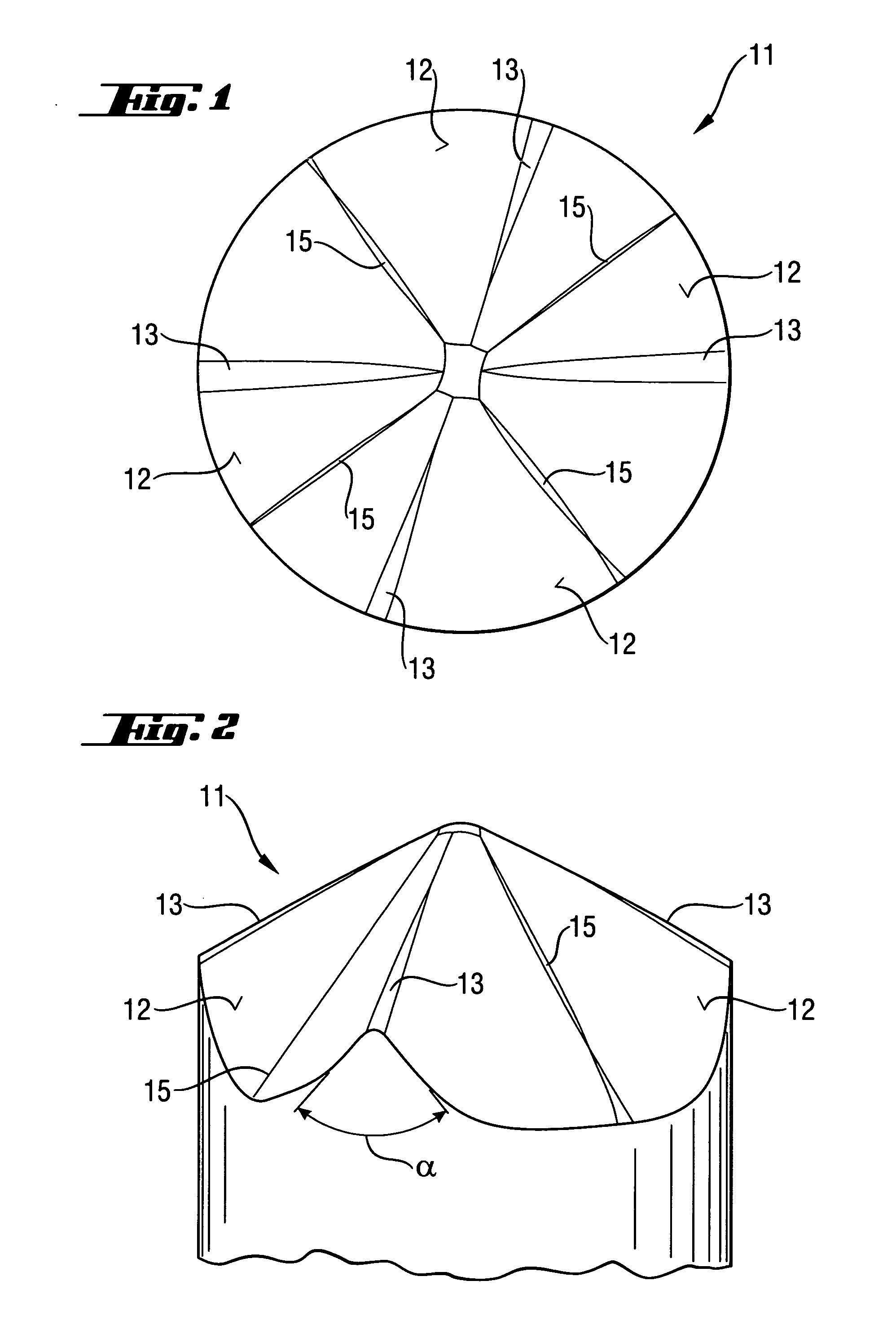
[0025] A centering tip 11, which is shown in FIGS. 1-2, forms part of a drilling head of a drill. The centering pin 11 is formed of four concave limiting surfaces 12 which stretch between auxiliary cutting edges 13. The deepest location of the concavity 15 of a concave limiting surface 12 extends essentially along a median line between two adjacent, linearly extending, auxiliary cutting edges 13. The wedge angle α of the linearly extending, auxiliary cutting edges 13 is smaller than the wedge angle of a minor cutting edge (not shown here, but corresponds to a wedge angle β of the minor cutting edge 17 shown in FIG. 3) or of a major cutting edge.

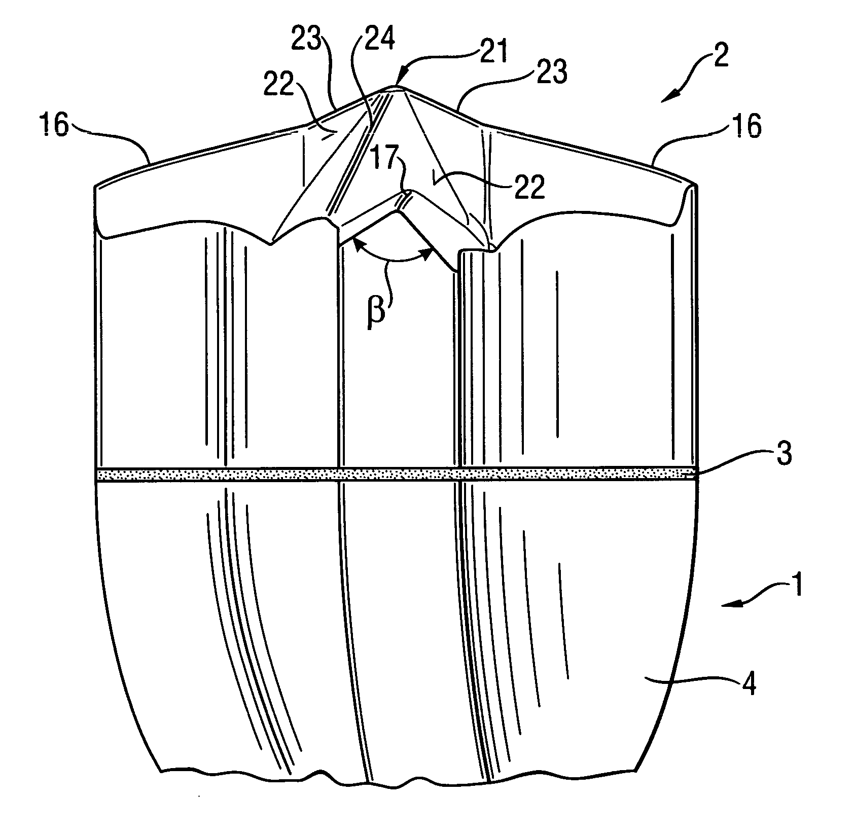
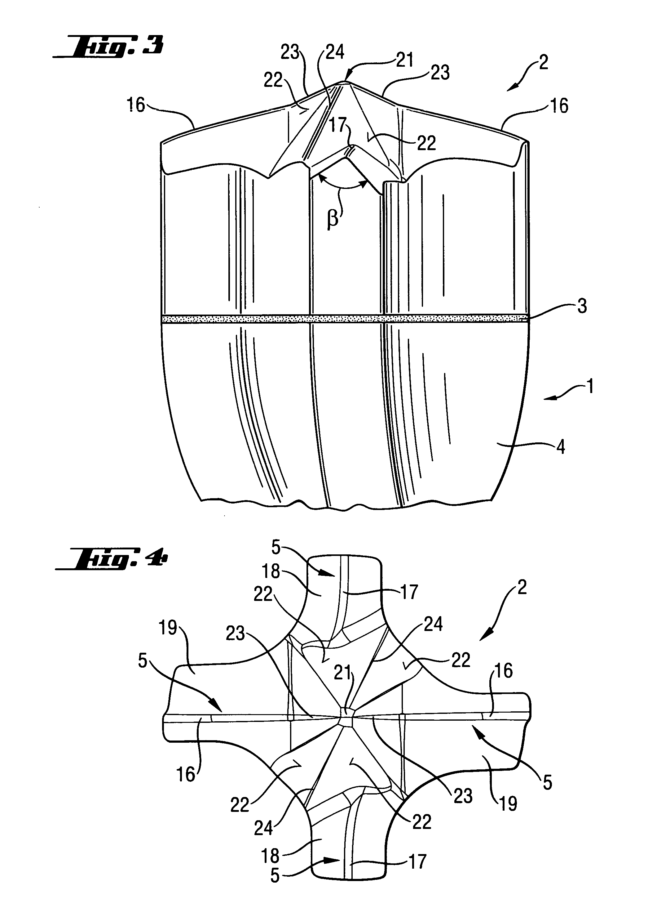
[0026] A drilling head 2 of a drill 1, which is shown in FIGS. 3-4, is formed as a one-piece body formed of a hard metal and is connected with the drill stem by a soldering connection 3. The drilling head 2 has four cutting bits 5 of which two cutting bit 5 are formed as major cutting bits 16 and two cutting bits 5 are formed as a major cutt...


PUM


Abstract

A drill in particular for a hammer drill for drilling in stone, concrete and the like includes a drilling head (2) formed as a hard material body with radial legs (18,19) and having at least three radially extending cutting bits (5) formed on the radial legs (18,19), and a centering tip (11;21) provided in a center of the hard material body and projecting beyond one of the cutting bits (16,17), with the centering tip (11;21) having concave limiting surfaces (12;22) stretching between the linearly extending auxiliary cutting edges (13;24,24).

Description

BACKGROUND OF THE INVENTION [0001] 1. Field of the Invention [0002] The present invention relates to a drill, in particular to a drill for a hammer drill for drilling in stone, concrete and the like, and including a drilling head formed of a hard material body with radial legs and having at least three radially extending cutting bits formed on the radial legs of the hard material body, and a centering tip provided in a center of the hard material body and projecting beyond one of the cutting bits, with the centering tip having linearly extending auxiliary cutting edges and limiting surfaces stretching between the auxiliary cutting edges. [0003] 2. Description of Prior Art [0004] The drilling head is generally formed of a hard material body that is obliquely secured on the end surface of a drill stem. Alternatively, instead of forming the entire drilling head of a hard material, only the bits are formed of a hard material as hard material inserts which are inserted in respective rece...

Claims


Application Information

Patent Timeline
IPC IPC(8): B23B51/02B28D1/14E21B10/44E21B10/46
CPCB23B51/02B23B2240/08B23B2240/16B23B2251/14B23B2251/18B23B2251/204B23B2251/207B23B2251/50B28D1/146E21B10/445
Inventor BATLINER, RAINERKOCH, OLAFHOFMANN, KARL-HEINZBRITTEN, WERNER
Owner HILTI AG
Why Eureka
Try Eureka