
Light emitting device

a technology of light emitting device and discharge tube, which is applied in the direction of discharge tube/lamp details, luminescnet screen, discharge tube/lamp details, etc., can solve the problems of changing the emitting characteristics of white led and hard to produce white led with color coordination

Active Publication Date: 2005-12-15
SEOUL SEMICONDUCTOR
View PDF44 Cites 140 Cited by
  • Summary
  • Abstract
  • Description
  • Claims
  • Application Information

AI Technical Summary

Benefits of technology

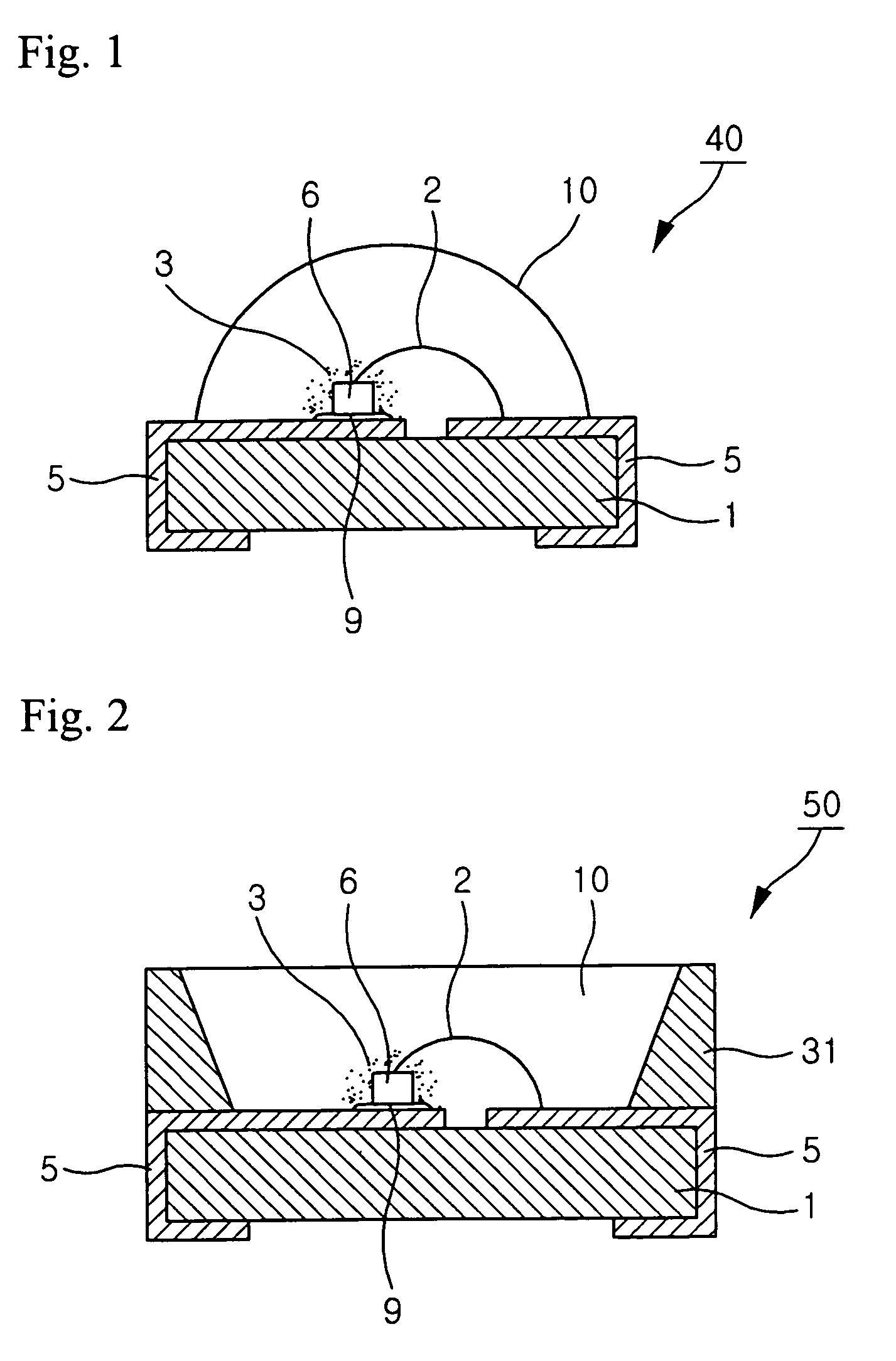
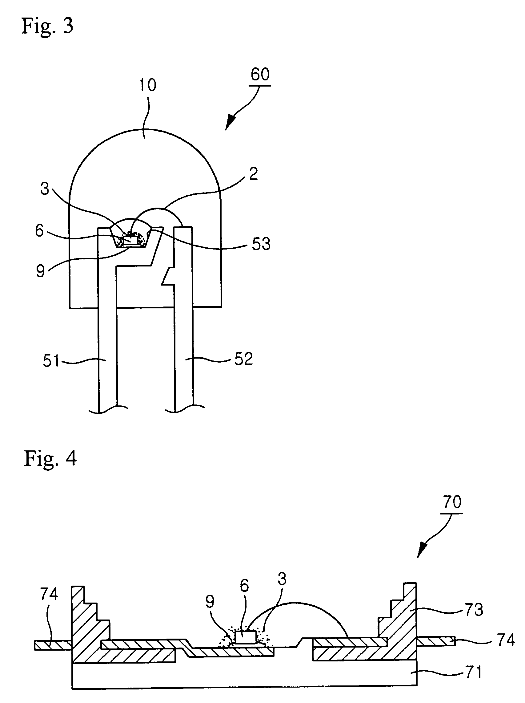
[0011] Further aspects of the invention may be apparent upon consideration of the following detailed description, taken in conjunction with the accompanying drawings, in which like reference characters refer to like parts throughout, and in which:

Problems solved by technology

Therefore, it is hard to produce the white LED with color coordination and color temperature that are similar to those of the visible light.
Moreover, phosphors which are used for white LEDs are usually unstable in the water, vapor or polar solvent, and this unstableness may cause changes in the emitting characteristics of white LED.

Method used


Image

  • Light emitting device
  • Light emitting device
  • Light emitting device

Examples


Embodiment Construction

[0019] Refer to the attached drawing, the wavelength conversion light emitting device is going to be explained in detail, and the light emitting device and the phosphor are separately explained for easiness of explanation as below.

[0020] (Light Emitting Device)

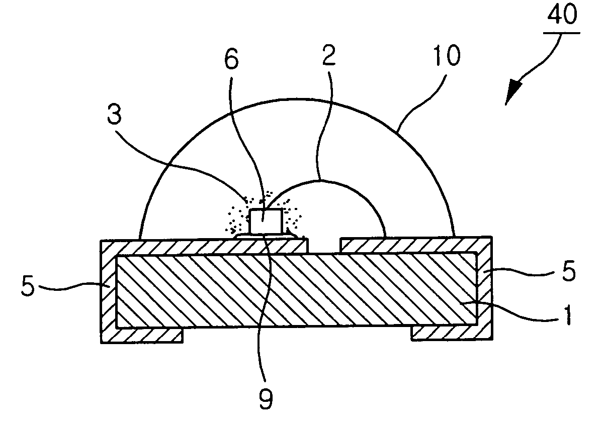
[0021]FIG. 1 shows a side cross-sectional view of an illustrative embodiment of a portion of a chip-type package light emitting device consistent with this invention. The chip-type package light emitting device may comprise at least one light emitting diode and a phosphorescent substance. Electrodes 5 may be formed on both sides of substrate 1. Light emitting diode 6 emitting light may be mounted on one of the electrodes 5. Light emitting diode 6 may be mounted on electrode 5 through electrically conductive paste 9. An electrode of light emitting diode 6 may be connected to electrode pattern 5 via an electrically conductive wire 2.

[0022] Light emitting diodes may emit light with a wide range of wavelengths, for example, fro...


PUM

PropertyMeasurementUnit
wavelengthaaaaaaaaaa
color temperatureaaaaaaaaaa
Color Rendering Indexaaaaaaaaaa

Abstract

A light emitting device can include a substrate, electrodes provided on the substrate, a light emitting diode configured to emit light, the light emitting diode being provided on one of the electrodes, phosphors configured to change a wavelength of the light, and an electrically conductive device configured to connect the light emitting diode with another of the plurality of electrodes. The phosphors can substantially cove at least a portion of the light emitting diode. The phosphor may include aluminate type compounds, lead and / or copper doped silicates, lead and / or copper doped antimonates, lead and / or copper doped germanates, lead and / or copper doped germanate-silicates, lead and / or copper doped phosphates, or any combination thereof.

Description

BACKGROUND OF THE INVENTION [0001] 1. Field of the Invention [0002] The invention relates to light emitting devices and more particularly to light emitting devices including at least one light-emitting diode and phosphor, the phosphor including lead and / or copper doped chemical compounds and converting the wavelength of light. [0003] 2. Description of the Related Art [0004] Light emitting devices (LEDs), which used to be used for electronic devices, are now used for automobiles and illumination products. Since light emitting devices have superior electrical and mechanical characteristics, demands for light emitting devices have been increased. In connection to this, interests in white LEDs are increasing as an alternative to fluorescent lamps and incandescent lamps. [0005] In LED technology, solution for realization of white light is proposed variously. Normally, realization of white LED technology is to put the phosphor on the light-emitting diode, and mix the primary emission from...

Claims


Application Information

Patent Timeline
Patent Type & Authority Applications(United States)
IPC IPC(8): C09K11/64C09K11/59C09K11/66C09K11/74C09K11/75C09K11/76C09K11/77F21V9/40H01L33/50H01L33/56H01L33/60H01L33/62
CPCC09K11/7734C09K11/7735C09K11/7792H01L33/502H01L2224/48091H01L2224/48247H01L2224/73265H01L2924/00014C09K11/7739C09K11/7738C09K11/756C09K11/753C09K11/7796C09K11/665C09K11/7756C09K11/7751C09K11/774C09K11/666C09K11/77344C09K11/77342C09K11/77
Inventor ROTH, GUNDULATEWS, WALTERLEE, CHUNG HOON
Owner SEOUL SEMICONDUCTOR
Learn More