[0009] The present invention seeks to reduce the detrimental effects on vehicle handling caused by braking, by acceleration, by simultaneous cornering and braking, and by simultaneous cornering and acceleration. The present invention constitutes an improvement of the
vehicle suspension system disclosed in applicant's prior U.S. Pat. No. 4,550,926 which simply concerns suspension systems for counteracting cornering forces imposed on vehicles. Enhanced vehicle handling is achieved by the present improved suspension system, in which not only do the roll couple and jacking couple oppose each other, thereby causing the
body roll to counteract the jacking effect, but also the pitch couple and the pitching couple oppose each other, thereby causing the body pitch to counteract the pitching effect, thus improving the cornering traction of the vehicle, the braking traction of the vehicle, the acceleration traction of the vehicle (especially in a front-wheel-drive-vehicle), the simultaneous cornering and braking traction of the vehicle, and the simultaneous cornering and acceleration traction of the vehicle. To this end, the
vehicle suspension system of the present invention is joined to the vehicle body to pivot about transverse and longitudinal axes located above the center of gravity of the vehicle body so that the cornering forces acting through the center of gravity tilt the body about the longitudinal axis inwardly into the curve and so that simultaneously the longitudinal braking or acceleration forces acting through the center of gravity tilt the body about the
transverse axis toward the rear or front, respectively, of the vehicle.
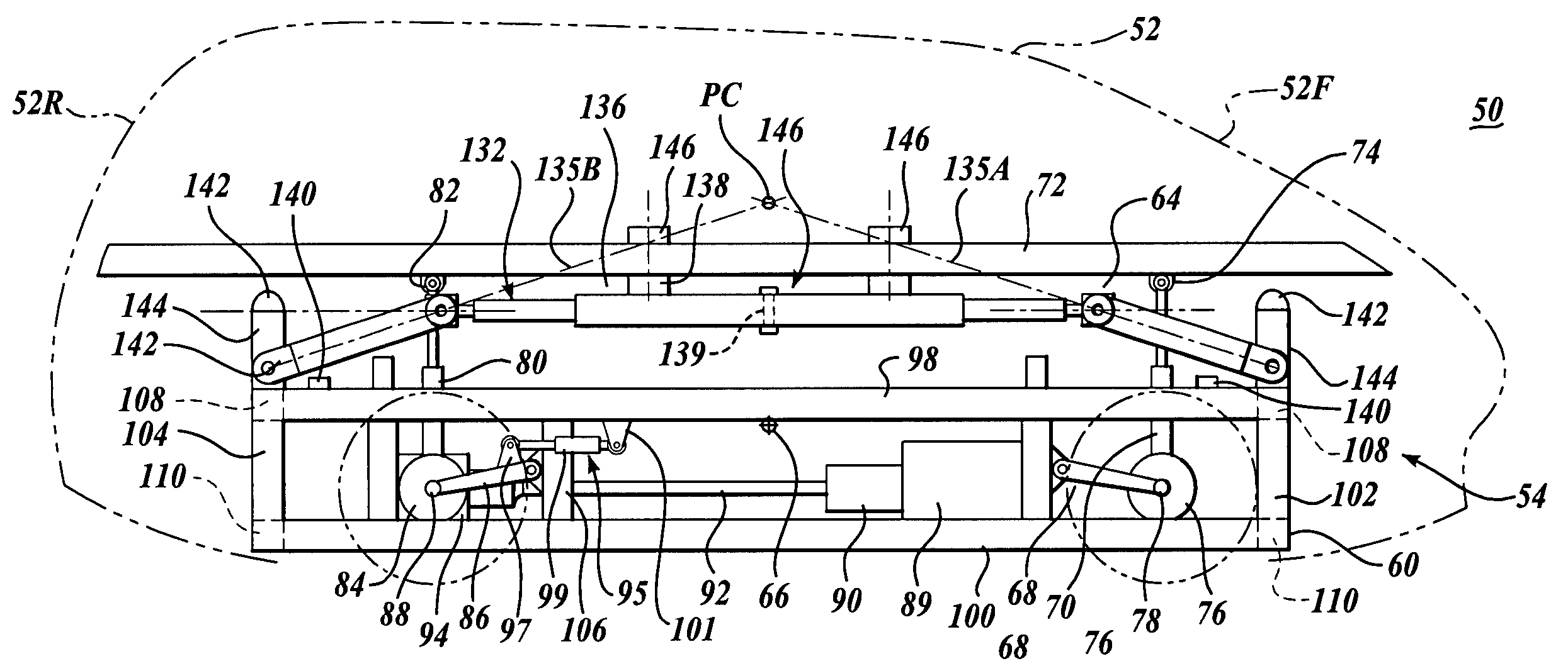
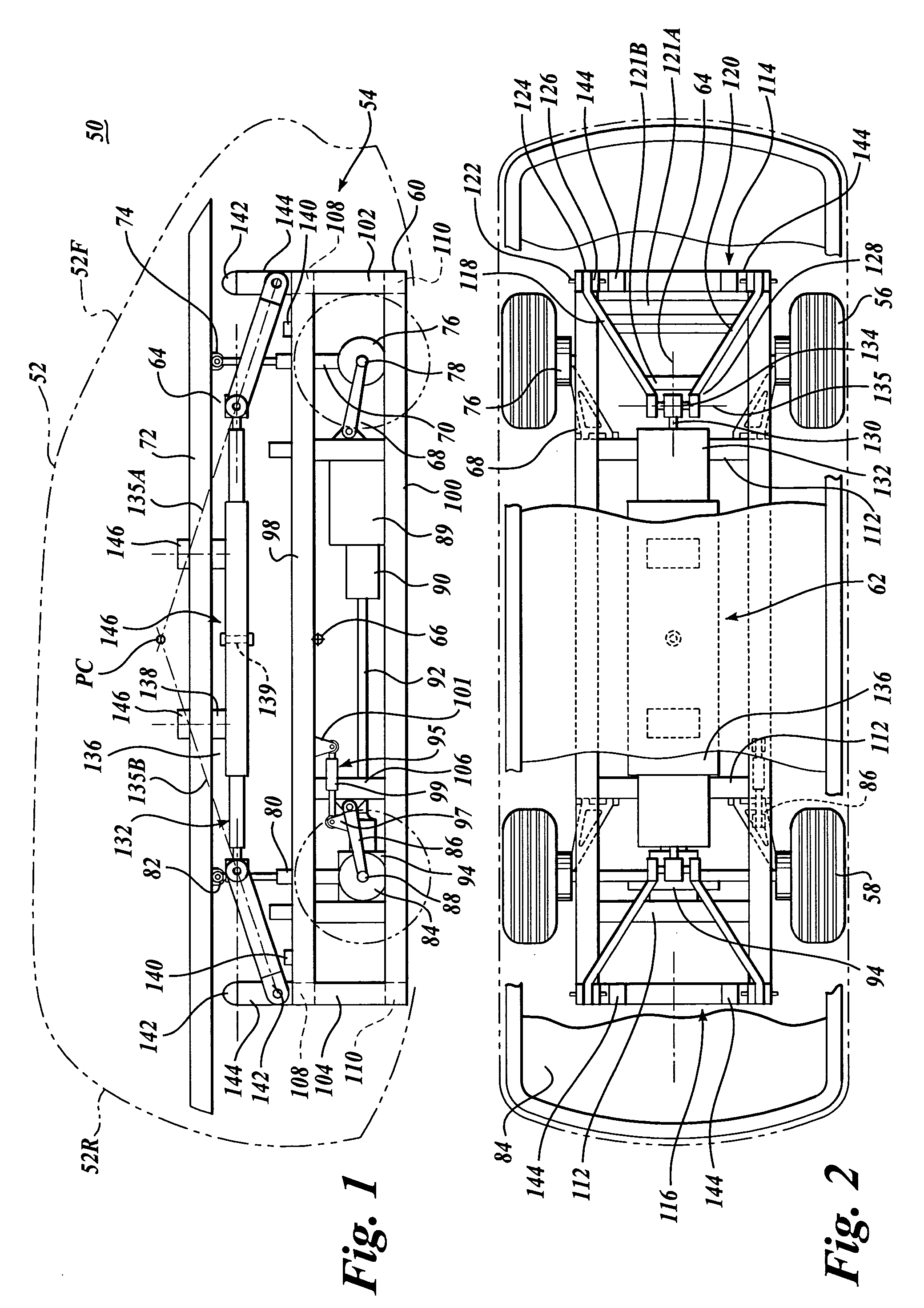
[0011] The tie structure is interconnected to the vehicle support means by suspension arms. Load control devices are utilized with the suspension arms to permit controlled relative movement therebetween. The suspension arms and load control devices together permit the tie structure and thus the longitudinal roll axis and the transverse pitch axis to shift relative to the vehicle support means in a controlled manner in the direction of the
resultant forces imposed on the body during cornering, braking and acceleration, thereby to preclude the roll axis, the pitch axis or the combined pitch and roll axis of the vehicle to serve as the roll reaction center, pitch reaction center or the combined roll and pitch reaction center of the vehicle. As a result, the jacking effect and pitching effect on the vehicle are reduced.
[0012] The capacities of the load control devices used to support the vehicle body on the wheel mounting members and the load control devices utilized at the interconnection of the tie structure to the wheel mounting members are selected so that the movement of the tie structure is less than the movement of the body. In particular, the capacities of the load control devices are selected to cause the roll stiffness and pitch stiffness of the tie structure to be greater than the roll stiffness and pitch stiffness of the body. As a result, not only does the vehicle
body roll and pitch in the opposite direction in comparison to a conventional vehicle thereby maintaining more even loading on the vehicle whole, but also simultaneously the jacking effect and pitching effect are reduced.
[0015] In another aspect of the present invention, the vehicle bumpers or other portions of the vehicle may be at least partially filled with a fluid so that when the bumper impacts against another vehicle or structure during a
crash, fluid will be expelled from the bumper in a controlled manner thereby to absorb a significant portion of the
crash energy. The fluid from the bumpers could be expelled into the environment or could be directed to components of a slide system which when receiving the fluid from the compressing bumper, could cause the body to move relative to the frame / tie structure in a controlled manner in reaction to the
crash occurring. Thus, a less abrupt force is imposed on the vehicle passengers, thereby reducing injury caused during the crash.
[0018] In a further aspect of the present invention, an “active” suspension system may be utilized between the body and the wheel hub carriers. Such
active suspension system may include powered actuators and sensors that sense cornering forces as well as braking and acceleration forces thereby to shift the body somewhat laterally outwardly during cornering, forwardly during braking, and rearwardly during acceleration, so that the
roll center does not serve as a roll reaction center when cornering and / or so that the pitch center does not serve as a pitch reaction center during braking or accelerating, thereby reducing the jacking effect and / or the pitching effect on the vehicle.

