Vehicle with movable and inwardly tilting safety body

a safety body and vehicle technology, applied in the direction of vehicular safety arrangments, bumpers, pedestrian/occupant safety arrangements, etc., can solve the problems of reducing the maximum braking capacity of the vehicle, and affecting the traction of one or more wheels. , to achieve the effect of reducing the jacking effect and/or the pitching effect of the vehicl

Active Publication Date: 2008-05-27
MACISAAC WILLIAM L
View PDF37 Cites 41 Cited by
  • Summary
  • Abstract
  • Description
  • Claims
  • Application Information

AI Technical Summary

Benefits of technology

[0009]The present invention seeks to reduce the detrimental effects on vehicle handling caused by braking, by acceleration, by simultaneous cornering and braking, and by simultaneous cornering and acceleration. The present invention constitutes an improvement of the vehicle suspension system disclosed in applicant's prior U.S. Pat. No. 4,550,926 which simply concerns suspension systems for counteracting cornering forces imposed on vehicles. Enhanced vehicle handling is achieved by the present improved suspension system, in which not only do the roll couple and jacking couple oppose each other, thereby causing the body roll to counteract the jacking effect, but also the pitch couple and the pitching couple oppose each other, thereby causing the body pitch to counteract the pitching effect, thus improving the cornering traction of the vehicle, the braking traction of the vehicle, the acceleration traction of the vehicle (especially in a front-wheel-drive-vehicle), the simultaneous cornering and braking traction of the vehicle, and the simultaneous cornering and acceleration traction of the vehicle. To this end, the vehicle suspension system of the present invention is joined to the vehicle body to pivot about transverse and longitudinal axes located above the center of gravity of the vehicle body so that the cornering forces acting through the center of gravity tilt the body about the longitudinal axis inwardly into the curve and so that simultaneously the longitudinal braking or acceleration forces acting through the center of gravity tilt the body about the transverse axis toward the rear or front, respectively, of the vehicle.
[0011]The tie structure is interconnected to the vehicle support means by suspension arms. Load control devices are utilized with the suspension arms to permit controlled relative movement therebetween. The suspension arms and load control devices together permit the tie structure and thus the longitudinal roll axis and the transverse pitch axis to shift relative to the vehicle support means in a controlled manner in the direction of the resultant forces imposed on the body during cornering, braking and acceleration, thereby to preclude the roll axis, the pitch axis or the combined pitch and roll axis of the vehicle to serve as the roll reaction center, pitch reaction center or the combined roll and pitch reaction center of the vehicle. As a result, the jacking effect and pitching effect on the vehicle are reduced.
[0012]The capacities of the load control devices used to support the vehicle body on the wheel mounting members and the load control devices utilized at the interconnection of the tie structure to the wheel mounting members are selected so that the movement of the tie structure is less than the movement of the body. In particular, the capacities of the load control devices are selected to cause the roll stiffness and pitch stiffness of the tie structure to be greater than the roll stiffness and pitch stiffness of the body. As a result, not only does the vehicle body roll and pitch in the opposite direction in comparison to a conventional vehicle thereby maintaining more even loading on the vehicle whole, but also simultaneously the jacking effect and pitching effect are reduced.
[0015]In another aspect of the present invention, the vehicle bumpers or other portions of the vehicle may be at least partially filled with a fluid so that when the bumper impacts against another vehicle or structure during a crash, fluid will be expelled from the bumper in a controlled manner thereby to absorb a significant portion of the crash energy. The fluid from the bumpers could be expelled into the environment or could be directed to components of a slide system which when receiving the fluid from the compressing bumper, could cause the body to move relative to the frame / tie structure in a controlled manner in reaction to the crash occurring. Thus, a less abrupt force is imposed on the vehicle passengers, thereby reducing injury caused during the crash.
[0018]In a further aspect of the present invention, an “active” suspension system may be utilized between the body and the wheel hub carriers. Such active suspension system may include powered actuators and sensors that sense cornering forces as well as braking and acceleration forces thereby to shift the body somewhat laterally outwardly during cornering, forwardly during braking, and rearwardly during acceleration, so that the roll center does not serve as a roll reaction center when cornering and / or so that the pitch center does not serve as a pitch reaction center during braking or accelerating, thereby reducing the jacking effect and / or the pitching effect on the vehicle.

Problems solved by technology

This resulting imbalance in the weight being carried by the forward and rearward wheels decreases the maximum braking capacity of the vehicle.
The foregoing loading changes on the vehicle wheels caused by cornering and braking will occur simultaneously when the vehicle's brakes are applied while cornering, thereby potentially causing even greater imbalance on the weights on the vehicle wheels than caused by cornering alone or braking alone.
This imbalance may result in the loss of substantially all of the traction of one or more wheels.
Placement of the roll reaction center and the pitch reaction center at a low elevation, however, results in the center of gravity of the body being located at a substantial distance above the roll center and pitch center, thereby increasing the magnitude of the roll couple and pitch couple.
The increase in the roll couple and pitch couple results in decreased stability of the vehicle, especially since in typical suspension systems the body roll and jacking effect and the body pitch and pitching effect are all cumulative, reducing the braking, acceleration and cornering ability of the vehicle.
As a consequence, all too often passengers are seriously injured, or even killed, during vehicle collisions, some of which do not occur at very high speeds.

Method used


Image

  • Vehicle with movable and inwardly tilting safety body
  • Vehicle with movable and inwardly tilting safety body
  • Vehicle with movable and inwardly tilting safety body

Examples


Embodiment Construction

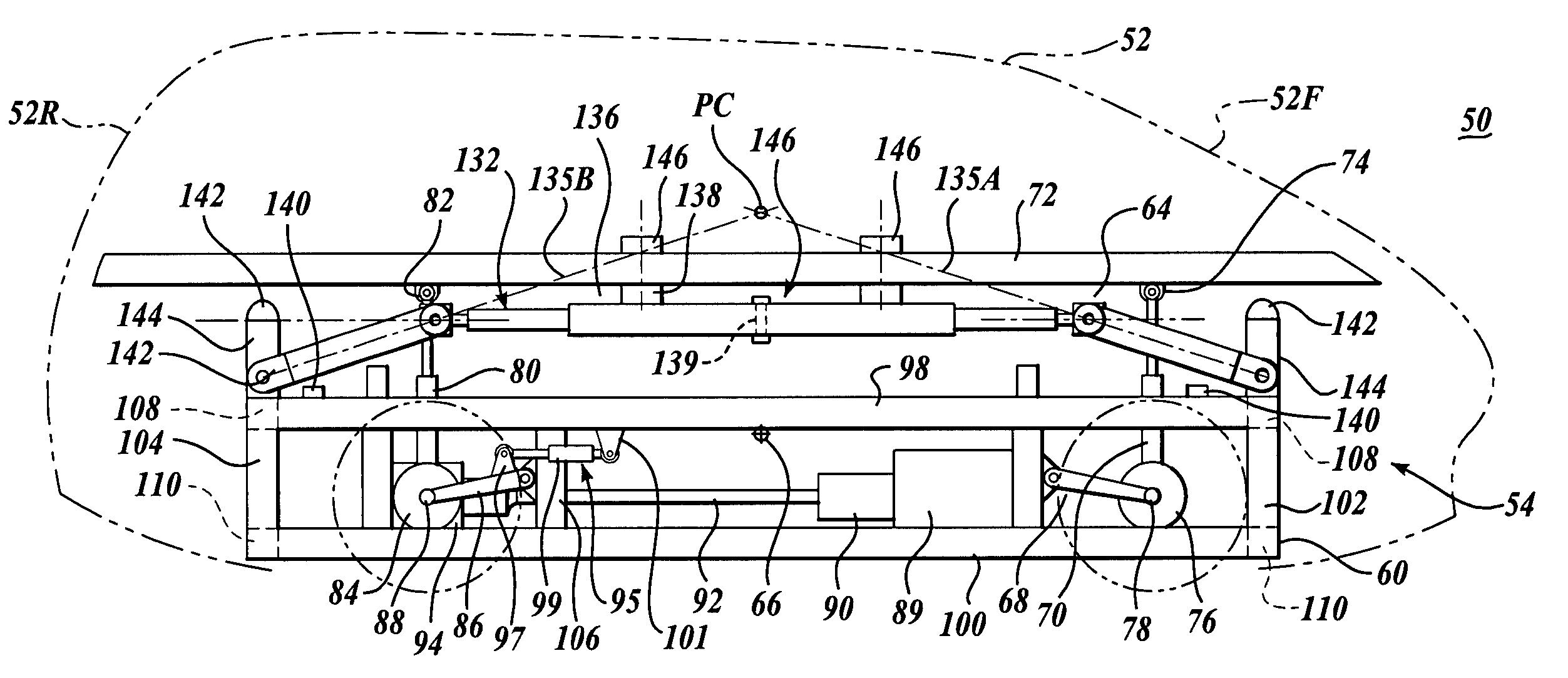
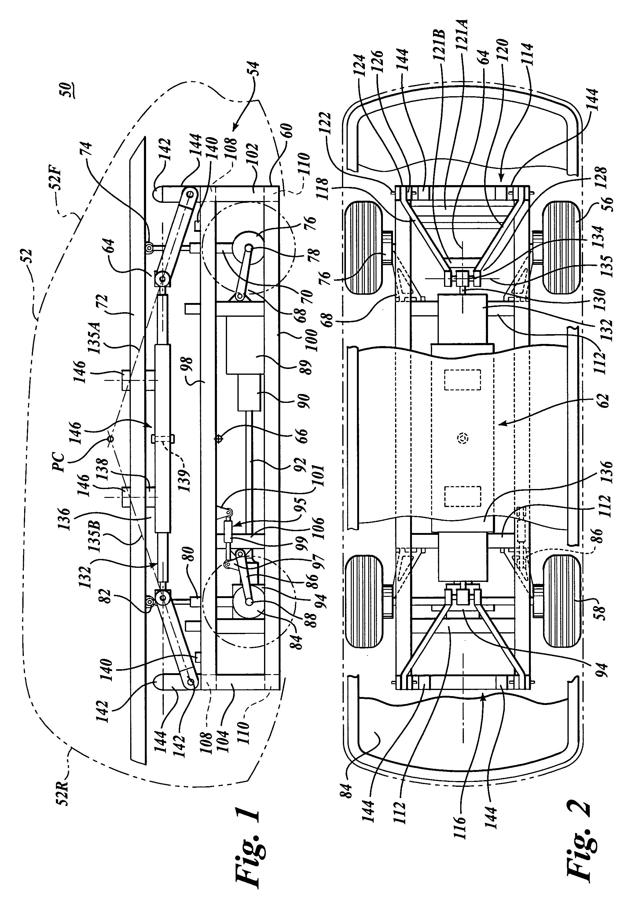
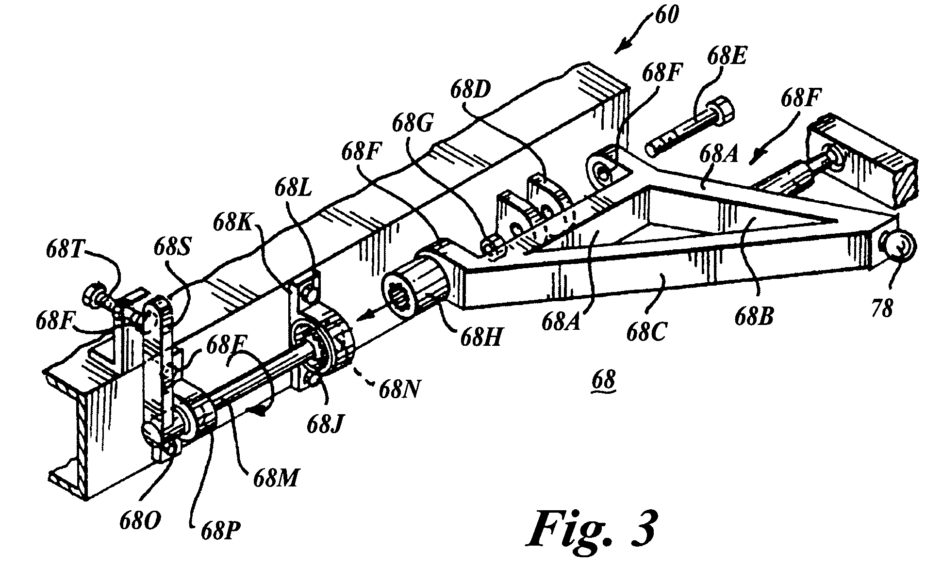
[0072]Referring initially to FIGS. 1 and 2, a vehicle 50 having a body 52 is shown as mounted on the suspension system 54 of the present invention, which in turn is supported on forward wheel assemblies 56 and rearward wheel assemblies 58. An elongated tie structure 60 is interposed between the vehicle body 52 and the wheel assemblies 56 and 58. The tie structure 60 may extend longitudinally along the lower elevation of the vehicle 50 and is interconnected to the body 52 through a slide assembly 62 to enable the body to slide longitudinally relative to the tie structure as well as pivot about a longitudinal axis 64 which is located at an elevation above the center of gravity 66 of the vehicle 50. The tie structure 60 is also connected to the wheels 56 and 58 by pivot arm assembles 68.

[0073]As used in the present application, the term “body” is intended to include a relatively rigid structure that may include a chassis, frame and / or the body thereof, and any additional supports and m...


PUM


Abstract

A suspension system for a vehicle (50c) having a body (52c) and a plurality of wheel support assemblies (56c, 58c) includes a tie structure (60c) interposed between the body and the wheel support assemblies. A first interconnection system (68c) interconnects the tie structure to the wheel support assemblies, and the second interconnection system (302) interconnects the tie structure and the body. The second interconnection system includes a plurality of link structures (304, 320) pivotally connected at one end to the tie structure, and pivotally connected at the opposite end to the body. Such link structures are oriented relative to the tie structure to extend towards a common point along a longitudinal axis (33B) of the tie structure.

Description

CROSS-REFERENCE TO RELATED APPLICATION[0001]This application claims the benefit of U.S. Provisional Application No. 60 / 412,045, filed Sep. 18, 2002.TECHNICAL FIELD[0002]The present invention relates to suspension systems for vehicles, and more particularly to suspension systems that counteract the lateral forces imposed on a vehicle during cornering and / or the longitudinal forces imposed on a vehicle during braking and acceleration.BACKGROUND OF THE INVENTION[0003]When negotiating a curve with a typical automotive-type vehicle, the resulting centrifugal forces tend to roll the vehicle body and associated chassis (hereinafter jointly referred to as “body”) about its roll center relative to the underlying suspension system, and also displace the body and suspension system laterally outwardly relative to the radial center of the curve, tending to cause the vehicle to pivot about its outer wheels. This latter tendency is commonly known in the motor vehicle art as the “jacking effect.” D...

Claims


Application Information

Patent Timeline
Patent Type & Authority Patents(United States)
IPC IPC(8): B60G17/005B60G1/00B60G3/01B60G3/20B60G7/00B60G13/16B60G17/016B60G21/00B60R19/18B60R21/00B62D39/00
CPCB60G3/01B60G3/20B60G7/008B60G13/16B60G17/0162B60G21/007B62D39/00B60G2200/14B60G2200/144B60G2204/1484B60G2204/30B60G2204/422B60G2204/4222B60G2204/62B60G2206/50B60R2019/1893B60G99/002
Inventor MACISAAC, WILLIAM L.
Owner MACISAAC WILLIAM L
Why Eureka
Try Eureka