Non-permeable pipe connector structure

Inactive Publication Date: 2005-12-15
SHU WEN CHIN
View PDF25 Cites 38 Cited by
  • Summary
  • Abstract
  • Description
  • Claims
  • Application Information

AI Technical Summary

Benefits of technology

[0005] The objective of the invention herein is to provide a non-permeable pipe connector structure, the design of which effectively prevents external material (such as vapor and miscellaneous substances, etc.) intrusion.
[0006] To obstruct the intrusion of external matter into the pipe connector, a ball bearing holder is disposed at the pipe connector, enabling even greater ball bearing durability and, furthermore, free rotation. A protective flang

Problems solved by technology

Conventional pipe connectors typically have minute crevices along the conjoinment surfaces between their fastened pipe connectors and coupling nipples that result in adverse consequences.
As such, the conjoinment surfaces are readily permeated by mois

Method used


Image

  • Non-permeable pipe connector structure
  • Non-permeable pipe connector structure
  • Non-permeable pipe connector structure

Examples


Example

[0013] The brief description of the drawings are accompanied below by the detailed description of the most preferred embodiments of the present invention.

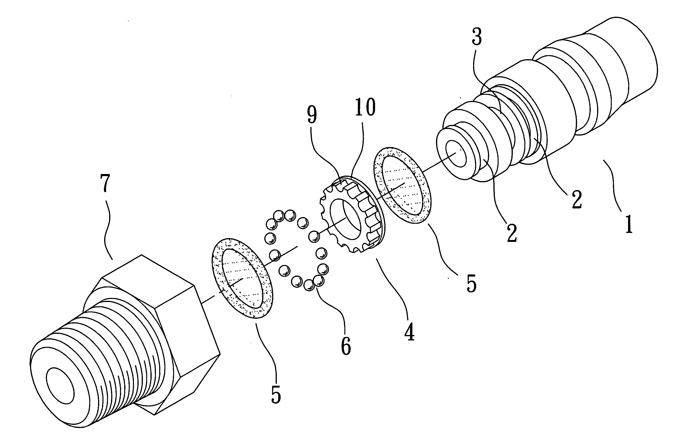
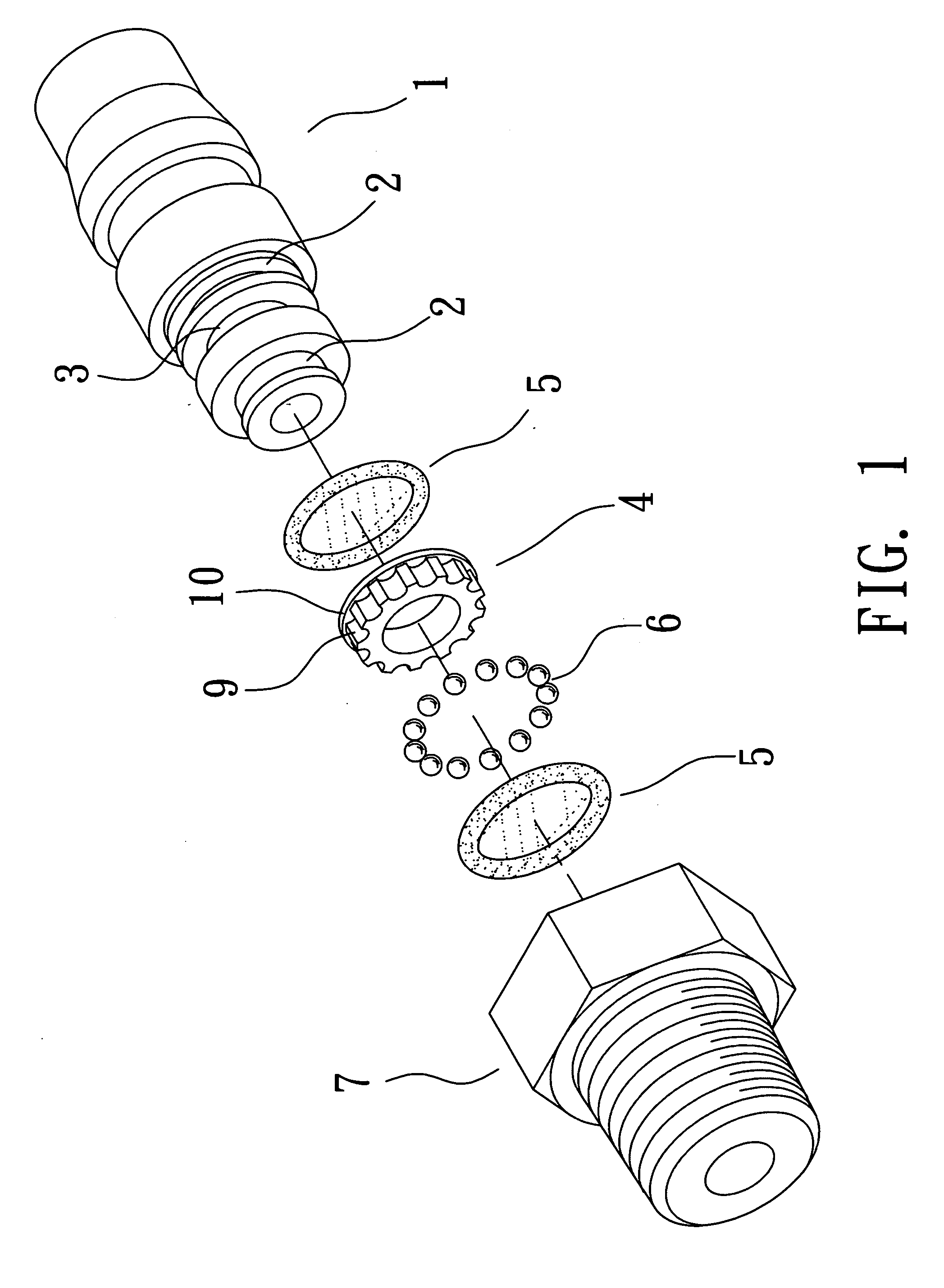
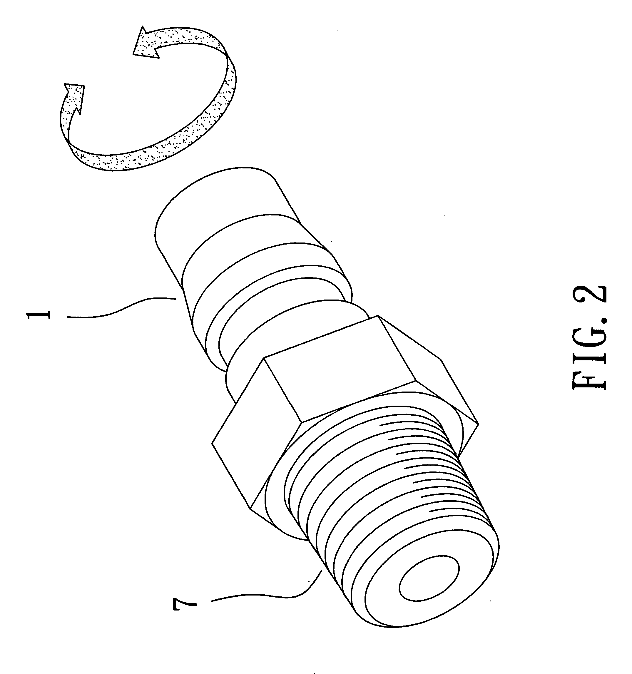
[0014] Refer to FIG. 1 , FIG. 2, and FIG. 3, the exploded drawing, the isometric drawing, and the orthographic drawing of the invention herein.

[0015] The non-permeable pipe connector structure herein is comprised of (as indicated in FIG. 1): a coupling nipple 1 having a plurality of annular grooves 2 at one extremity and a ball bearing race 3 between one annular groove 2 and another annular groove 2, the said ball bearing race 3 containing a ball bearing holder 4 inside such that a rubber sealing ring 5 is seated in the annular groove 2 and ball bearings 6 are nested on the ball bearing holder 4; a connector base 7 having a ball bearing groove 8 disposed inside that accommodates the ball bearings 6; the ball bearing holder 4 consists of a plurality of socket sections 9 that locate the ball bearings 6 and a protective flange 10 co...


PUM


Abstract

A non-permeable pipe connector structure, the design of which effectively prevents external material (such as vapor and miscellaneous substances, etc.) intrusion. To obstruct the intrusion of external matter into the pipe connector, a ball bearing holder is disposed at the pipe connector, enabling even greater ball bearing durability and, furthermore, free rotation. A protective flange is disposed as the bottom surface of the ball bearing holder such that when the coupling nipple and the connector base are fastened together, the protective flange effectively blocks external matter, thereby precluding entry to avert subsequent damage to the bearings. Furthermore, a rubber sealing ring sleeved onto the annular groove prevents vaporous or acid and alkaline substance intrusion into the bearings, and has safe defensive effectiveness.

Description

BACKGROUND OF THE INVENTION [0001] 1) Field of the Invention [0002] The invention herein relates to a non-permeable pipe connector structure, the design of which effectively prevents external material (such as vapor and miscellaneous substances, etc.) intrusion. [0003] 2) Description of the Prior Art [0004] Conventional pipe connectors typically have minute crevices along the conjoinment surfaces between their fastened pipe connectors and coupling nipples that result in adverse consequences. As such, the conjoinment surfaces are readily permeated by moisture that reaches the ball bearings and causes the drawback of ball bearing corrosion, the process continuing until the ball bearings are no longer capable of free rotation which directly affects pipe connector and coupling nipple turning capability. This is the shortcoming of the prior art. SUMMARY OF THE INVENTION [0005] The objective of the invention herein is to provide a non-permeable pipe connector structure, the design of whic...

Claims


Application Information

Patent Timeline
IPC IPC(8): F16L27/08F16L5/00
CPCF16L27/0828
Inventor SHU, WEN-CHIN
Owner SHU WEN CHIN
Why Eureka
Try Eureka