
Electrostatic detection apparatus and method, and coordinate detection program

Active Publication Date: 2005-12-15
ALPS ALPINE CO LTD
View PDF5 Cites 29 Cited by
  • Summary
  • Abstract
  • Description
  • Claims
  • Application Information

AI Technical Summary

Benefits of technology

[0010] The present invention has been made to solve the problems of the related art. An object of the present invention is to provide an electrostatic detection apparatus in which the accuracy of coordinate detection of a body to be detected is improved by making it unsusceptible to influences from areas other than a sensing area even when a routing-purpose extension line is provided in the vicinity of a sensing area.
[0011] Another object of the present invention is to provide an electrostatic detection apparatus in which the accuracy of coordinate detection is improved by preventing influences received from extension lines even when the routing-purpose extension lines are arranged densely in the vicinity of a sensing area.

Problems solved by technology

Consequently, an electrostatic capacitance is easily formed between the extension lines and the body to be detected, and moreover, the amount of the change thereof cannot be decreased, presenting a problem in that it is difficult to improve the accuracy of position detection of the body to be detected in the X and Y directions.

Method used


Image

  • Electrostatic detection apparatus and method, and coordinate detection program
  • Electrostatic detection apparatus and method, and coordinate detection program
  • Electrostatic detection apparatus and method, and coordinate detection program

Examples


first embodiment

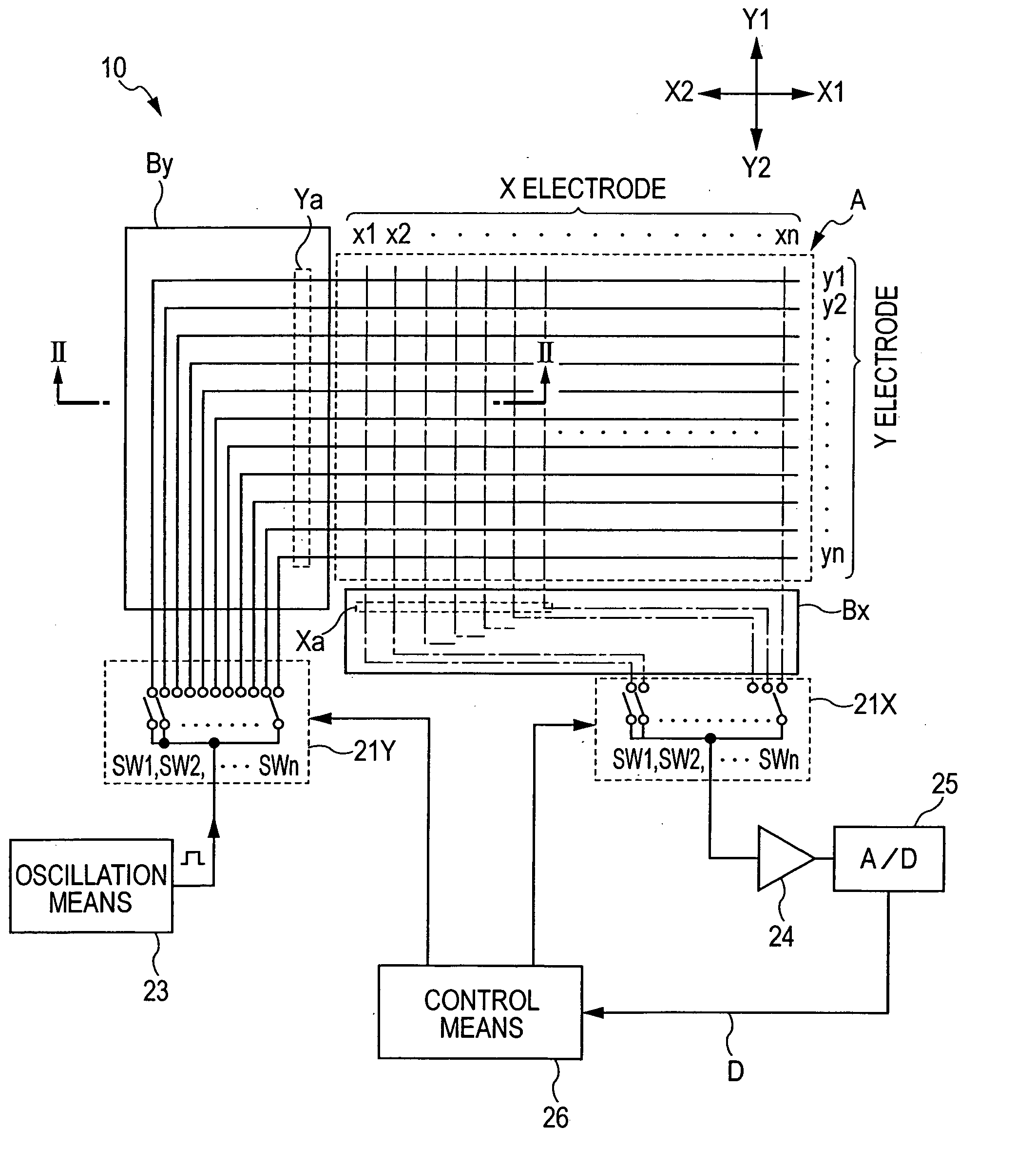
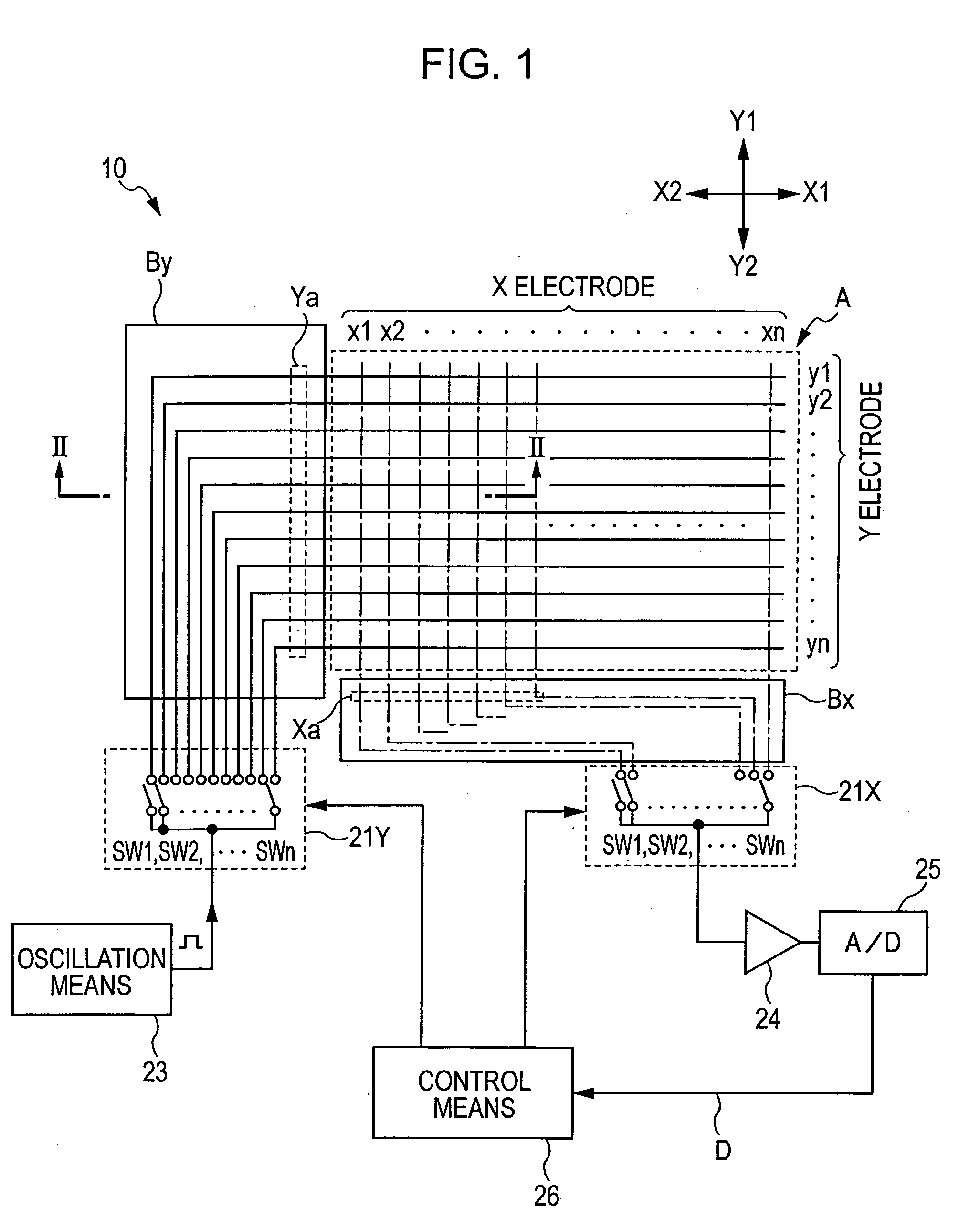
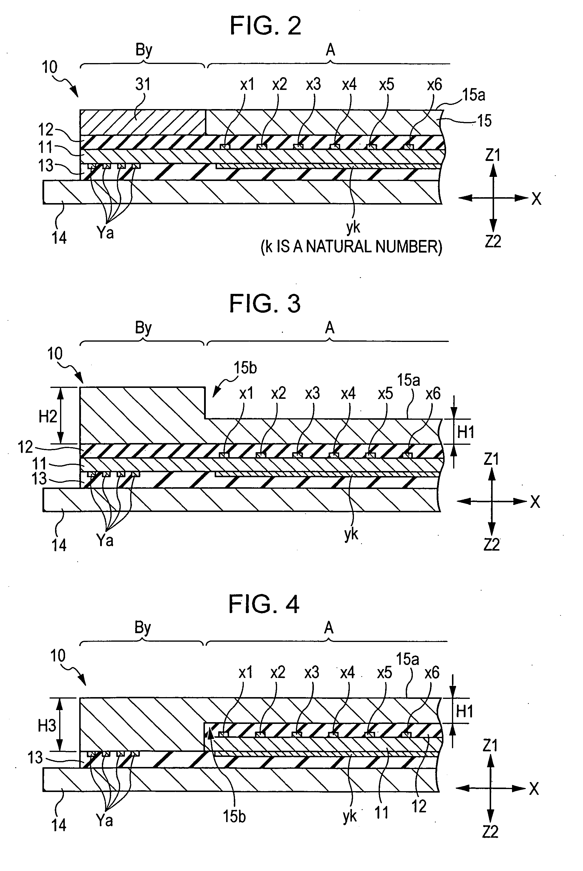
[0060] Here, in the electrostatic detection apparatus shown in FIG. 2, a shielding member 31 serving as electrostatic protection means is provided in the extension area By adjacent to the sensing area A. The shielding member 31 is formed from a metal plate made of a magnetic material and is fixed to the surface of the extension area By in such a manner as to cover the extension lines Ya.

[0061] The shielding member 31 is preferably configured to cover at least the vicinity of the sensing area A to which the body to be detected easily contacts, and more preferably covers the full length in which the extension lines Ya, which are end portions of the Y electrodes y1, y2, . . . , yn, are connected from the position outside the sensing area A to the switching means 21Y. It is preferable that the shielding member 31 be grounded in that still superior advantages can be expected.

[0062] As described above, as a result of covering the extension lines Ya using the shielding member 31, when the...

second embodiment

[0064] Next, the present invention will be described below with reference to FIG. 3.

[0065] The configuration of the electrostatic detection apparatus 10 shown in FIG. 3 is substantially the same as the configuration of the first embodiment. However, the electrostatic protection means provided in the extension area By differs from the shielding member 31.

[0066] When compared to the first embodiment, in the second embodiment, as a result of forming the plate thickness dimension H2 of the portion corresponding to the extension area By within the cover sheet 15 thicker than the plate thickness dimension H1 of the operation surface 15a, a step difference 15b is provided between them. H2 should preferably be 3 mm or more.

[0067] As described above, as a result of forming the plate thickness dimension H2 of the extension area By thicker than the other portion (the operation surface 15a), even when the body to be detected approaches or contacts the extension area By, similarly to that desc...

fifth embodiment

[0100]FIG. 9 is a schematic diagram similar to FIG. 7 showing an operation surface of a cover sheet according to the present invention.

[0101] In FIG. 9, a state is virtually shown in which a cross-shaped operation key (cross key) is formed on the operation surface 15a of the cover sheet 15.

[0102] For example, when the operation mode that uses the cross key is selected by the user while game software is being performed in a main apparatus (PC (Personal Computer) or the like) having incorporated therein the electrostatic detection apparatus 10 according to the present invention, in the computer 30, a program for a cross key from among a plurality of programs stored in the memory section 30B is loaded into the central processing section 30A, and is executed.

[0103] The operation of the electrostatic detection apparatus described in the second embodiment is identical to that of the first embodiment. That is, the central processing section 30A executes a program for a cross key, as show...


PUM


Abstract

A shielding member is provided as an electrostatic protection device in extension lines that extend from a sensing area to switching devices via extension areas correspondingly. As a result, even if a body to be detected such as a finger contacts the extension area, it is possible to reduce the amount of the change of an electrostatic capacitance with respect to the movement of the body to be detected. Therefore, it is possible to reduce influences exerted on data to be detected, and an electrostatic detection apparatus having improved coordinate detection accuracy can be provided.

Description

BACKGROUND OF THE INVENTION [0001] 1. Field of the Invention [0002] The present invention relates to an electrostatic detection apparatus used in a touch panel and a glide point and, more particularly, relates to an electrostatic detection apparatus in which detection accuracy is improved by making it unsusceptible to influences from areas other than a sensing area. [0003] 2. Description of the Related Art [0004] As a related art associated with an electrostatic detection apparatus according to the present invention, for example, a pad-type pointing device disclosed in, for example, U.S. Pat. No. 2003 / 0052867A1, is known. [0005] In U.S. Pat. No. 2003 / 0052867A1, an X electrode layer 20X formed of a plurality of X electrodes x1, x2, . . . , x15, x16 that extend in the X direction and that are arranged at a predetermined spacing in the Y direction on the under surface of a film substrate 10 is provided. An insulating film 12 is formed on the surface (under surface) of the X electrode l...

Claims


Application Information

Patent Timeline
IPC IPC(8): G01R27/26G03G15/08G06F3/046
CPCG06F3/046
Inventor SATO, TADAMITSUONO, SHUZO
Owner ALPS ALPINE CO LTD
Features
  • Generate Ideas
  • Intellectual Property
  • Life Sciences
  • Materials
  • Tech Scout
  • Unparalleled Data Quality
  • Higher Quality Content
  • 60% Fewer Hallucinations
Learn More