Optical system applicable to improving the dynamic range of Shack-Hartmann sensors

Inactive Publication Date: 2005-12-15
RGT UNIV OF CALIFORNIA
View PDF7 Cites 176 Cited by
  • Summary
  • Abstract
  • Description
  • Claims
  • Application Information

AI Technical Summary

Benefits of technology

[0020] Another embodiment of the invention provides for shifting of the microlens array in relation to the collection of detectors. This allows a given mi

Problems solved by technology

High aberration of a light beam can be produced by, for example: strong atmospheric disturbance of a light beam from a an astronomical source; defects in an optical device through which the light beam passes in an optics quality assurance or measurement system; or by optical defects in an eye (which is after all another form of an optical device) that is being evaluated in an ophthalmic-analysis system.
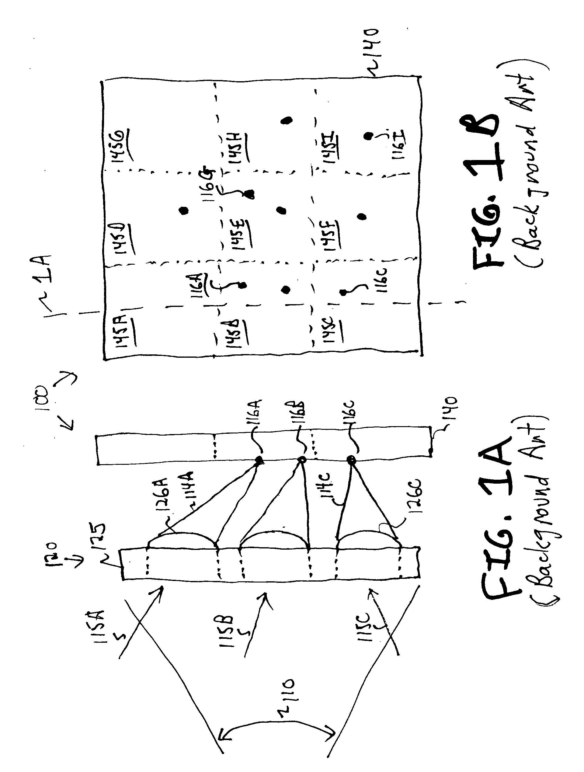
A problem arises, as shown in FIGS. 1A and 1B, when the wavefront aberration of the light beam incident on a microlens is large enough that the focal point falls outside of the microlens' assigned area and falls into the assigned area of a different, typically adjacent microlens.
In such a situation, a false reading is likely to occur because the detector has no way to associate a focal-point reading with

Method used


Image

  • Optical system applicable to improving the dynamic range of Shack-Hartmann sensors
  • Optical system applicable to improving the dynamic range of Shack-Hartmann sensors
  • Optical system applicable to improving the dynamic range of Shack-Hartmann sensors

Examples


Example

[0029] The descriptions, discussions and figures herein illustrate technologies related to the invention and show examples of the invention and of using the invention. Known methods, procedures, systems, circuits, or elements may be illustrated and described without giving details so as to avoid obscuring the principles of the invention. On the other hand, details of specific embodiments of the invention are described, even though such details may not apply to other embodiments of the invention.

[0030] Some descriptions and discussions herein use abstract or general terms including but not limited to receive, present, prompt, generate, yes, or no. Those skilled in the art use such terms as a convenient nomenclature for components, data, or operations within a computer, digital device, or electromechanical system. Such components, data, and operations are embodied in physical properties of actual objects including but not limited to electronic voltage, magnetic field, and optical ref...


PUM


Abstract

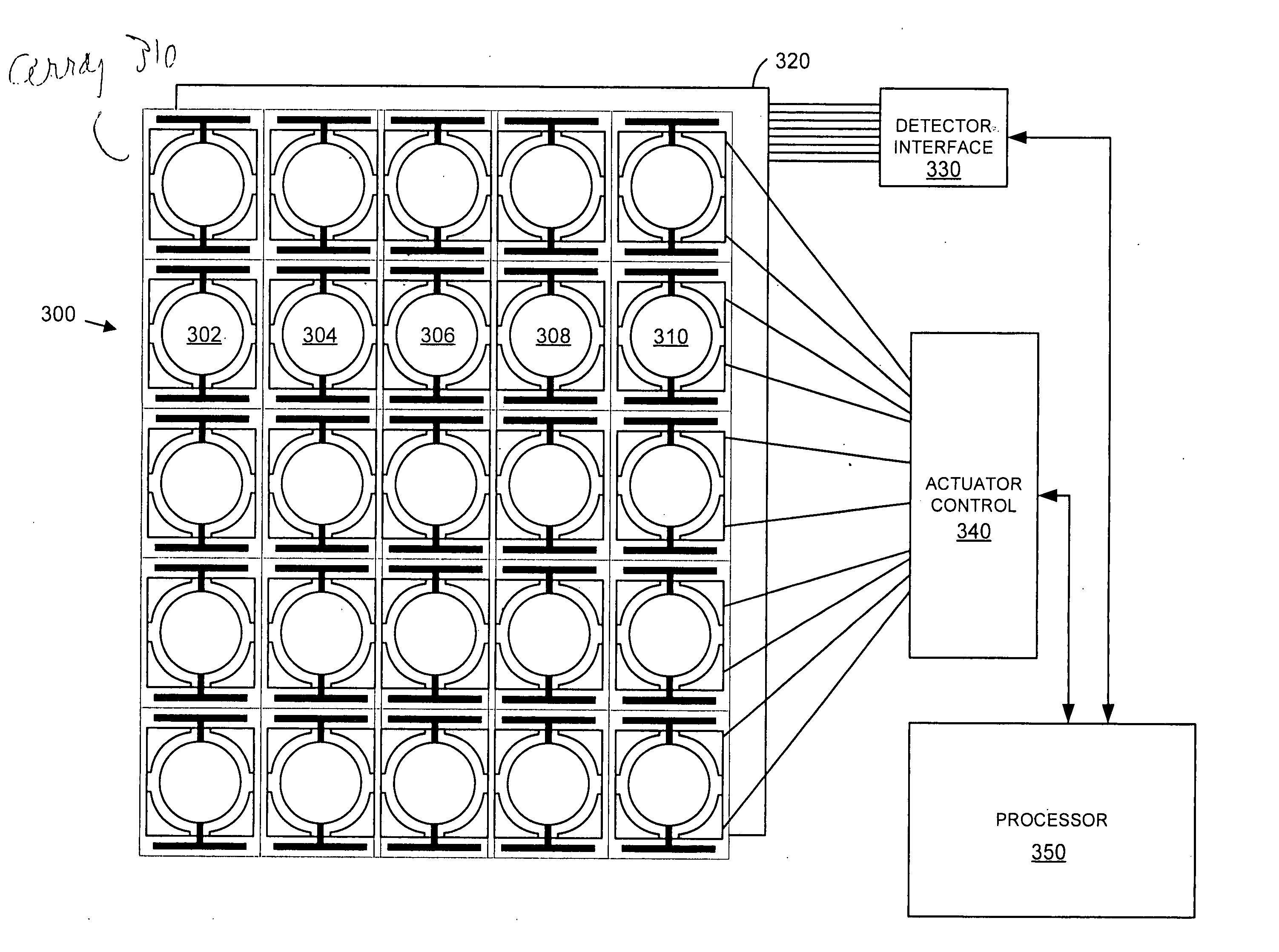
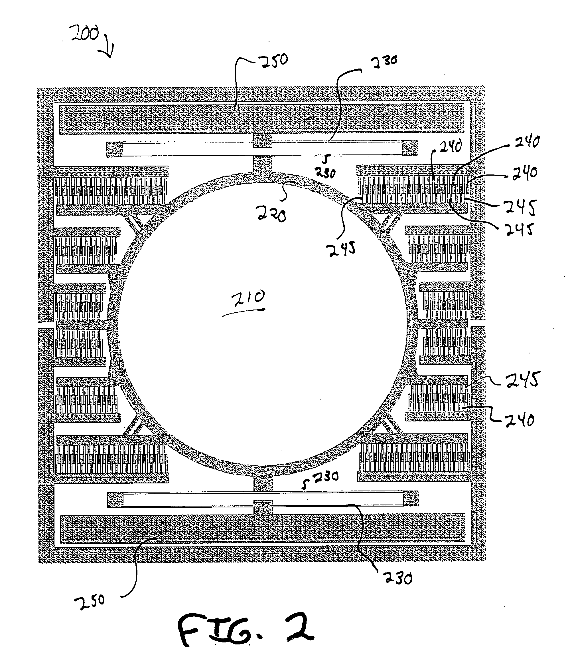
An addressable array of lenses is disclosed. Two electrical connections per row address specific lenses within that row. Carriages support individual lenses, thus forming resonant units with frequencies unique within each row. A voltage, having the same frequency as a selected resonant unit is applied. The selected lens produces a resonating image. Testing has verified proper resonance addressing within a 5-by-5 array of microlenses. The array can be applied to a Shack-Hartmann (SH) sensor. To compensate for errant images formed outside of their image area, resonating images are identified by a processor. The array thus improves the dynamic range of the wavefront aberration that can be measured by an SH sensor. The inventors currently estimate the improvement over conventional designs to be about a factor of 30.

Description

REFERENCE TO RELATED APPLICATIONS [0001] This application claims priority from Provisional U.S. Patent Application 60 / 572,794 “Micro-Electromechanical Array Using Resonant Frequency for Device Selection”, by Choo et al. This application is incorporated herein by reference for all purposes.BACKGROUND OF THE INVENTION [0002] Micro-scale lenses include, for example, lenses having a diameter ranging from about 4 millimeters (mm) down to about 20 micrometers or microns (μm). Microlenses have many valuable applications, which include but are not limited to, monitors for light beam distortion or wavefront aberrations for ophthalmic analysis systems and for adaptive optics systems for astronomy. Specifically, one type of useful application of a regularly spaced array of microlens is a Shack-Hartmann (SH) sensor. [0003] Shack-Hartmann sensors are widely used to measure, and even to continuously monitor and correct, wavefront aberrations. Adaptive optical systems perform real-time corrections...

Claims


Application Information

Patent Timeline
IPC IPC(8): B29D11/00G02B26/08G02B27/09G02B27/10G02B27/46
CPCB29D11/00365G02B26/0875G02B27/46G02B27/0961G02B27/0933
Inventor CHOO, HYUCKMULLER, RICHARD S.
Owner RGT UNIV OF CALIFORNIA
Why Eureka
Try Eureka