Broken-yoke iron core of three-phase amorphous alloy transformer

An amorphous alloy and transformer technology, applied in the field of broken yoke iron core, can solve the problems of complicated coil replacement, increased no-load loss of iron core, complicated processing technology, etc., and achieve the advantages of overcoming winding difficulties, small no-load loss and high filling factor Effect

Inactive Publication Date: 2014-12-31
SHANGHAI ZHIXIN ELECTRIC AMORPHOUS +6
View PDF9 Cites 0 Cited by
  • Summary
  • Abstract
  • Description
  • Claims
  • Application Information

AI Technical Summary

Problems solved by technology

The iron core structure of this transformer has many disadvantages. First, the rectangular cross-section of the iron core column consumes 11.1% more copper than the circular cross-section in the case of the same number of coil turns; secondly, each transformer has more single-frame iron cores (by Composed of single row or double row), the oblique seams at the disconnection of the iron yoke will increase, and the reluctance will also increase accordingly. When the transformer is running, under the action of the AC magnetic field, these seams are very likely to cause multiple Low-frequency vibrating, which makes a lot of noise
In addition, the magnetic flux density in the iron yoke of this iron core structure is 1.155 times the magnetic flux density in the iron core leg, so it also leads to an increase in the no-load loss of the iron core
[0003] In addition, the existing triangular wound core transformers are all closed, and the coil winding requires a professional winding machine, which makes the equipment investment of the production enterprise relatively large, the manufacturing efficiency is low, the processing technology is complicated, and the coil replacement is complicated.

Method used


Image

  • Broken-yoke iron core of three-phase amorphous alloy transformer
  • Broken-yoke iron core of three-phase amorphous alloy transformer
  • Broken-yoke iron core of three-phase amorphous alloy transformer

Examples


Embodiment Construction

[0018] In order to better understand the technical solution of the present invention, the following will be described in detail through specific embodiments in conjunction with the accompanying drawings:

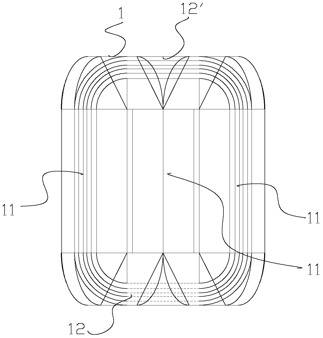
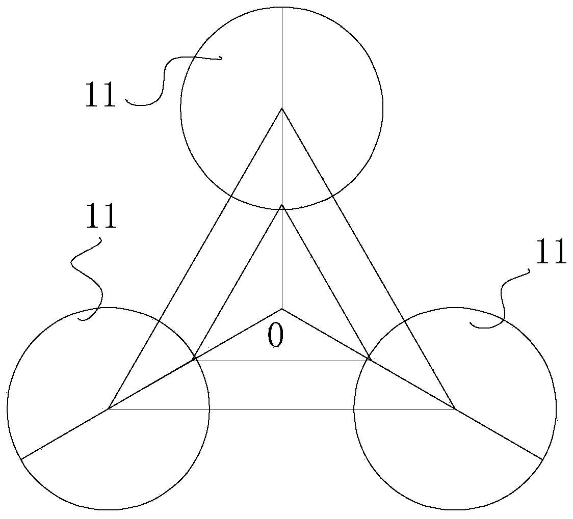
[0019] see Figure 1 to Figure 5 , a broken yoke core of a three-phase amorphous alloy transformer of the present invention includes three unit cores 10 having the same shape and size, and each unit core 10 is composed of left and right unit core columns 13, 13' and upper and lower units with the same height A rectangular frame formed by unit iron yokes 14, 14', wherein:

[0020] A unit iron yoke 14' can be opened on each unit iron core 10;

[0021] Each unit core 10 is formed by nesting a plurality of unit cores 100 respectively having left and right unit iron core columns and upper and lower unit iron yokes, so that the left and right unit iron core columns 13, 13' and the upper and lower unit iron yokes 14, The cross section of 14' is basically a semicircle (circumscrib...


PUM


Abstract

The invention discloses a broken-yoke iron core of a three-phase amorphous alloy transformer. The broken-yoke iron core comprises three unit iron cores, wherein upper unit iron yokes on the unit iron cores can be opened; each unit iron core is formed by nesting multiple single iron cores one by one, the cross section of a single iron core column of each single iron core and the cross section of a single iron yoke are both in parallelogram shapes, and the cross sections of each unit iron core column and each unit iron yoke are enabled to be basically in semicircular shapes. According to the broken-yoke iron core disclosed by the invention, each of three iron core columns is respectively formed by carrying out mutual butt joint between the diameter of the cross section of a left unit iron core column of one unit iron core and the diameter of the cross section of a right unit iron core column of the other unit iron core, the cross sections of the three iron core columns are basically in circular shapes, and an equilateral triangle shape is formed by circle centers of the cross sections of the three iron core columns. The broken-yoke iron core disclosed by the invention has the advantages that the performance is excellent, the noise is low, the materials are saved, and the cost is low; more importantly, transformer coils can be independently coiled, and great convenience is provided for the sleeving of the transformer coils.

Description

technical field [0001] The invention relates to a broken yoke core of a three-phase amorphous alloy transformer. Background technique [0002] Existing three-phase amorphous alloy (silicon steel) transformer core columns all have a rectangular cross-section, and the core structure is mostly four-frame and five-column or three-frame and three-column. The iron core structure of this transformer has many disadvantages. First, the rectangular cross-section of the iron core column consumes 11.1% more copper than the circular cross-section in the case of the same number of coil turns; secondly, each transformer has more single-frame iron cores (by Composed of single row or double row), the oblique seams at the disconnection of the iron yoke will increase, and the reluctance will also increase accordingly. When the transformer is running, under the action of the AC magnetic field, these seams are very likely to cause multiple Vibrates at a low frequency, which creates a lot of noi...

Claims


Application Information

Patent Timeline
IPC IPC(8): H01F27/24H01F27/25H01F1/153
Inventor 于春雷顾小虎凌健张士岩杨庆福
Owner SHANGHAI ZHIXIN ELECTRIC AMORPHOUS
Why Eureka
Try Eureka