Time of flight sensor

Pending Publication Date: 2020-04-02
PHOTONIC VISION LTD
View PDF5 Cites 6 Cited by
  • Summary
  • Abstract
  • Description
  • Claims
  • Application Information

AI Technical Summary

Benefits of technology

The invention combines a special sensor and a new way of operating it to overcome poor fill factor and high readout noise issues. This allows for long range operation with high precision, at a low cost. The use of a charge coupled device as the sensor increases efficiency and allows for lower power lasers.

Problems solved by technology

Automotive driver assistance and collision warning systems pose specific measurement challenges because they require long range (>100 m) distance measurement with both high precision and high spatial resolution.
Time of flight based light radar (lidar) sensors are a promising technology to deliver this combination of capabilities but existing solutions are costly and have yet to deliver the required performance particularly when detecting objects of low reflectivity.
However, whilst such sensors can provide high spatial resolution their maximum range performance is limited by random noise sources including intrinsic circuit noise and particularly the shot noise generated by ambient light.
This fill factor limitation reduces the sensitivity of the sensor to light, requiring a higher power and costlier light source to overcome.
An additional an important limitation is that this technique is limited to providing only one measurement of distance per pixel and so is unable to discriminate the reflections from solid objects and atmospheric obscurants such as fog, dust, rain and snow thus restricting the use of such sensors technologies to indoor, covered environments.
However, the difficulties and costs associated with manufacturing dense arrays of APDs and the yield losses incurred when hybridising them with ROIC has meant that the resolution of such sensors is limited (e.g. 256×32 pixels) and their prices are very high.
However, the quantum efficiency of such sensors is poor due to constraints of the CMOS process and their fill factor is poor due to the need for TDC circuitry at each pixel leading to very poor overall photon detection efficiency despite the very high gain of such devices.
Also avalanche multiplication based sensors can be damaged by optical overloads (such as from the sun or close specular reflectors in the scene) as avalanche multiplication in the region of the optical overload signal can lead to extremely high current densities, risking permanent damage to the device structure.
However, if the delay lines have enough elements to capture the reflected laser pulse from long range objects with good time and hence distance resolution, then they occupy most of the pixel area leaving little space for a photosensitive area.
Typically, this poor fill factor more than offsets the noise benefits of the slower speed readout and so high laser pulse power is still required, significantly increasing the total lidar sensor cost.
To try to overcome this problem some workers have integrated an additional amplification stage between the photosensitive region and the delay line but this introduces noise itself, thus limiting performance.

Method used


Image

  • Time of flight sensor
  • Time of flight sensor
  • Time of flight sensor

Examples


Embodiment Construction

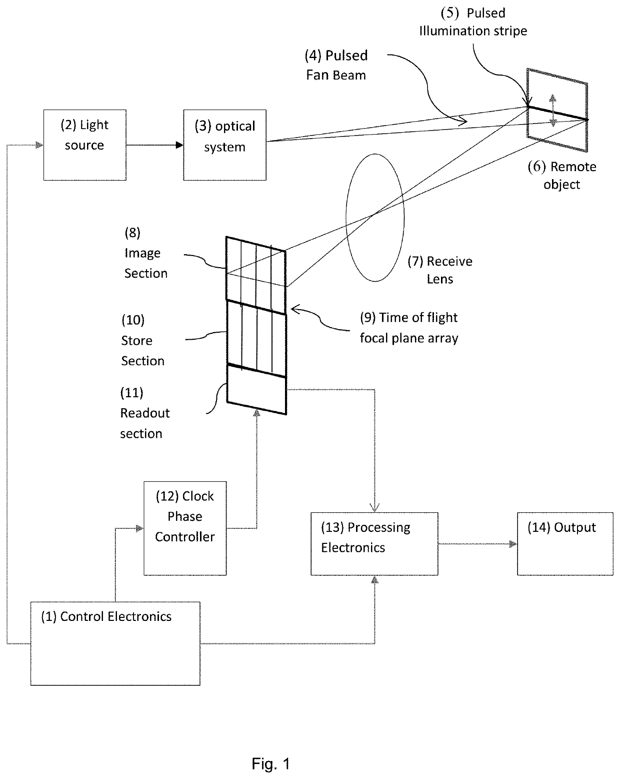
[0054]One embodiment is shown in FIG. 1.

[0055]Control electronics (1) are configured to control light source (2) and associated optical system (3) to emit a pattern of light with a pre-defined combination of spatial and temporal characteristics into the far field.

[0056]In the simplest embodiment shown in FIG. 1, the spatial distribution of the emitted light is a fan beam (4) whose location in a direction orthogonal to the long axis of the beam is adjustable under control of the control electronics (1) and the temporal characteristics of the light are a short pulse, where the timing of the light pulse is set by the control electronics (1).

[0057]This combination of spatial and temporal characteristics will create a pulsed stripe of illumination (5) across the surface of any remote object (6).

[0058]Receive lens (7) is configured to collect and focus the reflected pulse of light from this stripe of illumination (5) onto the photosensitive image section (8) of a focal plane array (FPA) d...


PUM


Abstract

A time of flight distance measurement system has a light emitter (8) emitting a pulsed fan beam and a time of flight sensor (6) which may be a CCD with a photosensitive image region, a storage region not responsive to light and a readout section. Circuitry is arranged to control the time of flight sensor (6) to capture image data of the pulsed illumination stripe along a row of pixels and to transfer the captured image data to the storage section. The circuitry adjusts the phase of the clocking of the image region with respect to the emission of a pulsed fan beam to collect a plurality of image illumination stripes at a respective plurality of phase shifts; and a processor combines the data from the plurality of image illumination stripes at the plurality of phase shifts to determine the distance to the object.

Description

FIELD OF INVENTION[0001]The invention relates to a time of flight distance sensor and method of use.BACKGROUND TO THE INVENTION[0002]Accurate and fast surface profile measurement is a fundamental requirement for many applications including industrial metrology, machine guarding and safety systems.[0003]Automotive driver assistance and collision warning systems pose specific measurement challenges because they require long range (>100 m) distance measurement with both high precision and high spatial resolution.[0004]Time of flight based light radar (lidar) sensors are a promising technology to deliver this combination of capabilities but existing solutions are costly and have yet to deliver the required performance particularly when detecting objects of low reflectivity.[0005]To address this problem, much effort has been expended on developing pixelated focal plane arrays able to measure the time of flight of modulated or pulsed infra-red (IR) light signals and hence measure 2D or...

Claims


Application Information

Patent Timeline
IPC IPC(8): G01S17/36H01L27/148G01S17/89G01S7/486
CPCH01L27/148G01S17/36G01S7/4863G01S17/89G01S7/00
Inventor MORCOM, CHRISTOPHER JOHN
Owner PHOTONIC VISION LTD
Why Eureka
Try Eureka