

Wrench for an engine clutch of a radio control model
a technology of clutch and radio control, applied in the field of wrenches, can solve the problems of easy wear of the centrifugal lever (b>4/b>), and users' difficulty in using ordinary hand tools, such as pliers and screwdrivers, to exchange worn centrifugal levers
- Summary
- Abstract
- Description
- Claims
- Application Information
AI Technical Summary
Benefits of technology
Problems solved by technology
Method used
Image

Examples
Embodiment Construction
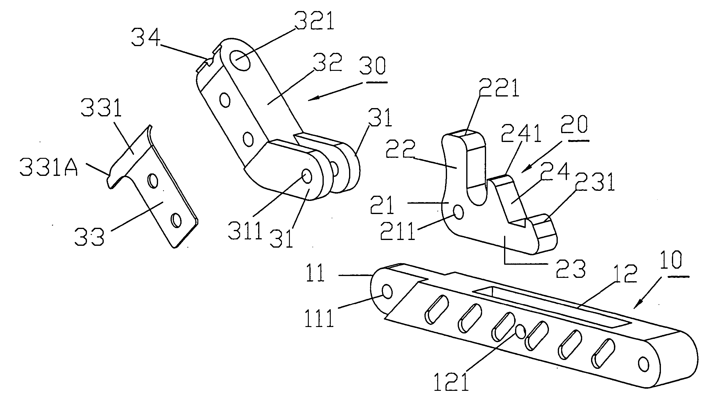
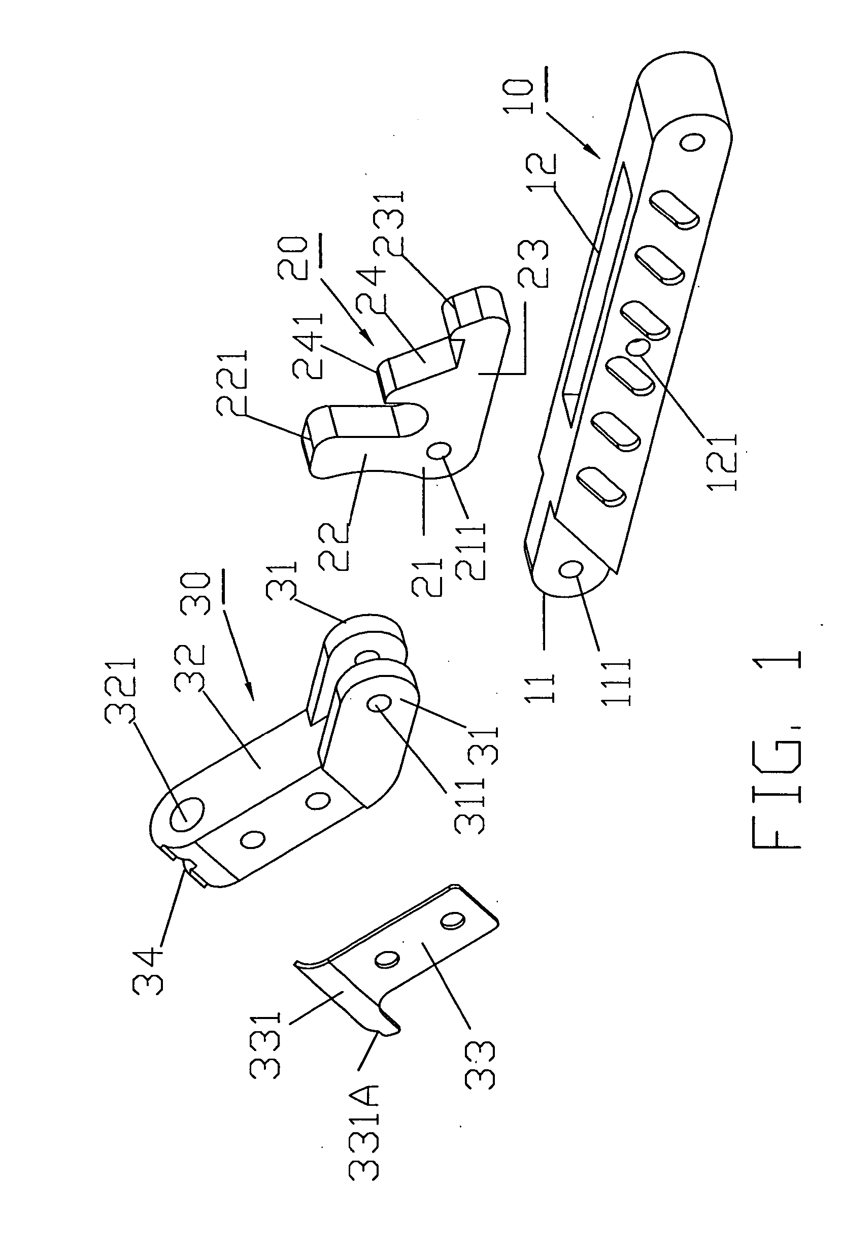
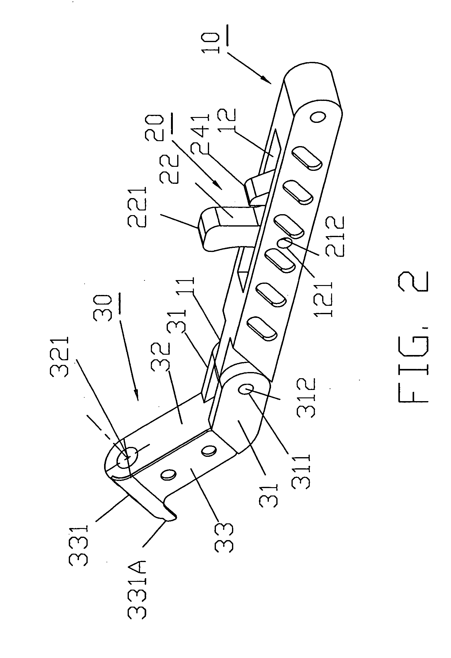
[0021] Referring to the drawings and initially to FIGS. 1 and 2, a wrench for an engine clutch of a radio control model in accordance with the present invention comprises handle (10), a control unit (20) pivotally mounted in a middle portion of the handle (10) and a drive unit (30) pivotally connected to one end of the handle (10).
[0022] The handle (10) includes an extension (11) longitudinally extending from one end of the handle (10) and having a through hole (111) laterally extending through the extension (11). A receiving space (12) is longitudinally defined in the middle portion of the handle (10). A pivot hole (121) is defined in the middle portion of the handle (10) and laterally extends through the handle (10).
[0023] The control unit (20) is partially pivotally received in the receiving space (12) in the handle (10). In the preferred embodiment of the present invention, the control unit (20) has an F-shape. The control unit (20) includes shank (23) having a first end (21) ...
PUM
| Property | Measurement | Unit |
|---|---|---|
| power | aaaaa | aaaaa |
| centrifugal force | aaaaa | aaaaa |
| friction force | aaaaa | aaaaa |
Abstract
Description
Claims
Application Information