
Gear product and method for manufacturing the same

a technology for gear teeth and products, applied in the field of gear products, can solve the problems of wasting tools, affecting the quality of tools, etc., and achieves the effect of reducing labor intensity, reducing labor intensity, and reducing labor intensity

Inactive Publication Date: 2005-12-22
O OKA CORP
View PDF5 Cites 13 Cited by
  • Summary
  • Abstract
  • Description
  • Claims
  • Application Information

AI Technical Summary

Benefits of technology

[0006] It is an object of the present invention to provide a gear product and a method for manufacturing the same, in which by forming a crowning on any one of tooth surfaces engaging each other, it is able to reduce the trouble of process for forming a crowning, to abbreviate machining time, to reduce the dispersion of accuracy due to the abrasion of tools and the wastage cost of tools, to enhance efficiency greatly, and to lower costs.
[0007] It is another object of the present invention to reduce a machining time for forming a crowning and to provide a technology for forming a crowning by forging.
[0019] The present invention (the eleventh invention described in claim 11) provides a technology which enables to reduce machining time for forming a crowning and a technology for forming a crowning by the utilization of forging means, and provides a gear product having a plurality of tooth formed at a predetermined pitch on an outer peripheral surface of a disc-form body thereof, in which tooth forms of all teeth are unified to one pattern selected from a plurality of pattern in which a crowning is formed at at least one of four parts of every both ends on each tooth surface of the teeth and the crowning is not formed at the other of the four parts thereof.
[0030] Moreover, in case that the crowning is formed by forging, the present invention has an advantage that there is no need of cutting, it is efficient and there is no dispersion.

Problems solved by technology

In the step of forming crownings at four parts of every tooth by cutting, there were problems that it took a lot of time and trouble, the dispersion of accuracy due to the abrasion of tools and the wastage cost of tools could not be ignored.

Method used


Image

  • Gear product and method for manufacturing the same
  • Gear product and method for manufacturing the same
  • Gear product and method for manufacturing the same

Examples


Embodiment Construction

[0040] A gear product and a method for manufacturing the same according to the present invention will now be described with reference to the drawings.

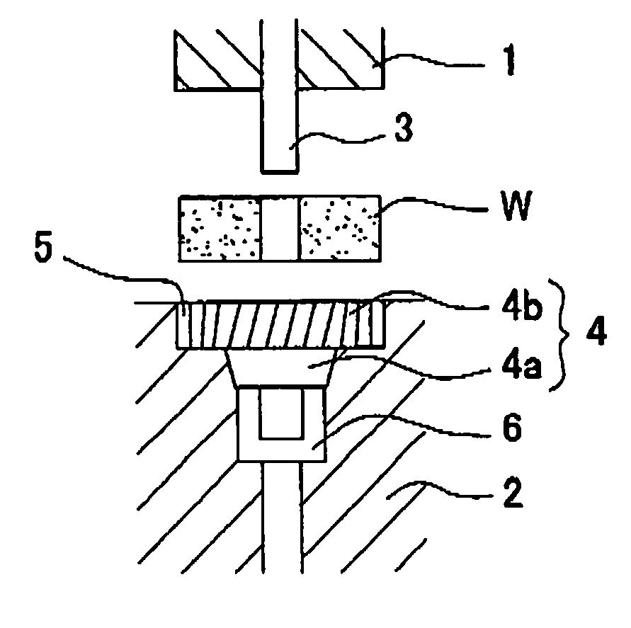
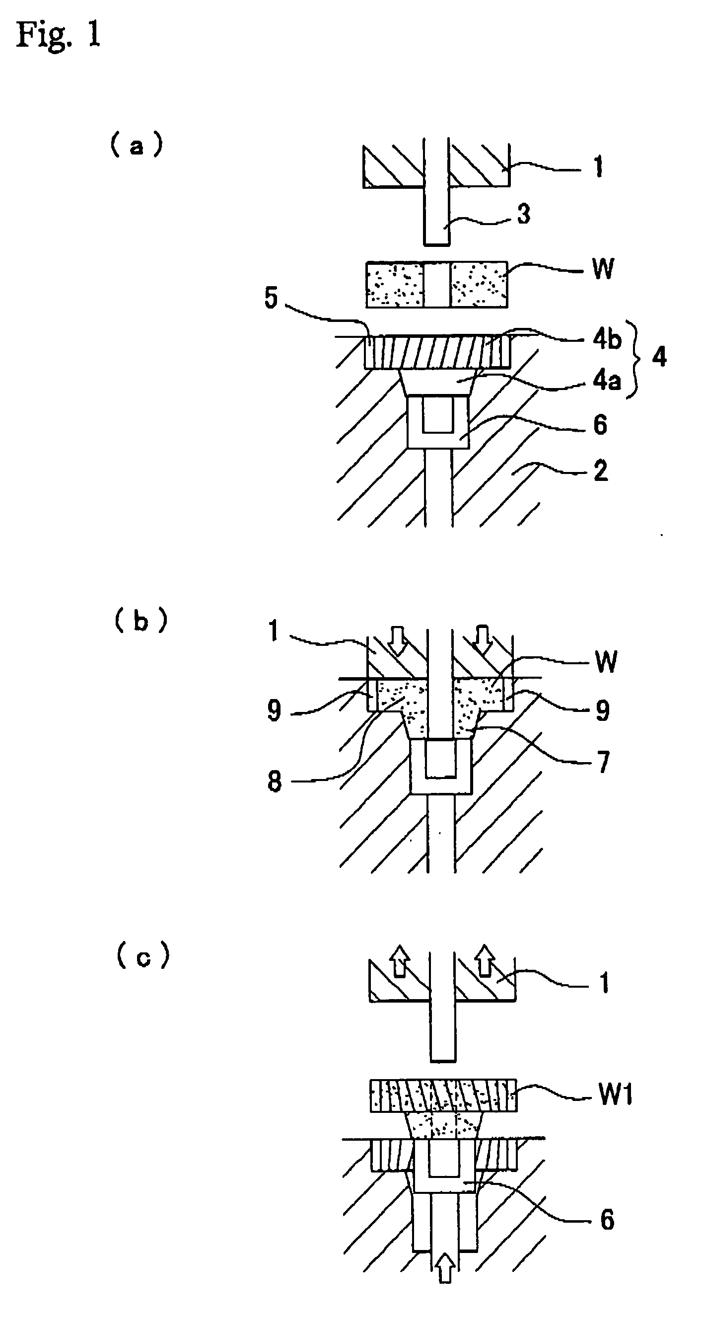
[0041]FIG. 1 shows a forming step of the first molded article. In FIG. 1, 1 is a cope, 2 is a drag and a mandrel 3 is projected at the center of a pressure surface of the cope 1.

[0042] Meanwhile, a cavity 4, which is two-stage form composed of a disc-form like boss forming part 4a for forming a boss and a disc-form gear forming part 4b for forming a gear, is provided in the drag 2. A tooth form or profile 5 for forming helical gear is formed on an inner peripheral surface corresponding to the gear forming part 4b and a knockout sleeve 6 is provided on a bottom surface so as to project movably.

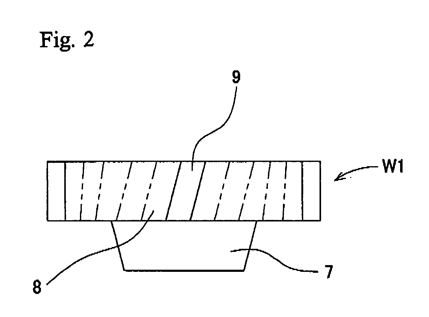
[0043] When a disc-form work W set at an opening of the cavity 4 is depressed by the cope 1 (as shown in FIG. 1(b)), the work W is compressed into the cavity 4, the cavity 4 is filled with the work W, a boss part 7 is formed at the bottom surfa...


PUM

PropertyMeasurementUnit
thicknessaaaaaaaaaa
pressureaaaaaaaaaa

Abstract

In a gear product, a plurality of tooth having a crowning formed in a pattern unified to one pattern selected from fourteen patterns comprising four patterns in which a crowning is formed at one of an upper end part A or lower end part B of an upper inclined surface 91, an upper end part C or a lower end part D of a lower inclined surface 92, six patterns in which crownings are formed at two parts thereof and four patterns in which crownings are formed with three parts thereof, are formed at an equal pitch on an outer peripheral surface of a gear part. In a helical gear 9, a combination pattern of an upper part A of an upper side tooth surface 91 and a lower part D of a lower tooth surface 92 or a pair of an upper part C of the lower tooth surface 92 and a lower part D of the upper tooth surface 92 is formed by forging device.

Description

TECHNICAL FIELD [0001] The present invention relates to a gear product (including a gear with missing teeth) having a plurality of tooth formed at a predetermined pitch on an outer peripheral surface of a disc-form part thereof. BACKGROUND ART [0002] Crowning F,F,F,F are formed at four parts of every both end parts of tooth surfaces of tooth form of a gear product so that tooth thickness may gradually decrease from the center part thereof toward both ends of tooth, as shown in FIG. 9 and tooth surfaces engaging each other may always maintain the point contact thereof. A gear product with crowning was manufactured by forming a product having a tooth form without crowning by cutting or forging, and cutting four end parts of tooth surfaces of every tooth so as to form crowning. [0003] In the step of forming crownings at four parts of every tooth by cutting, there were problems that it took a lot of time and trouble, the dispersion of accuracy due to the abrasion of tools and the wastag...

Claims


Application Information

Patent Timeline
Patent Type & Authority Applications(United States)
IPC IPC(8): B21K1/30B23F19/00B23P15/14F16H55/08
CPCB21K1/30B21K1/305Y10T74/19949F16H55/0886Y10T29/49462B23F19/002
Inventor OOKA, JUNICHI
Owner O OKA CORP
Learn More