

Knife having removable blade
- Summary
- Abstract
- Description
- Claims
- Application Information
AI Technical Summary
Benefits of technology
Problems solved by technology
Method used
Image

Examples
Embodiment Construction
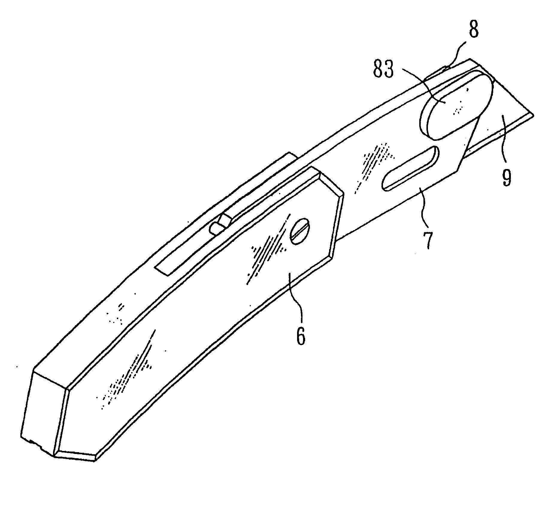
[0025] With reference now to the drawings, and particularly FIGS. 4 and 5, there is shown a knife having a blade holder 7 for receiving a removable blade 9 within a slot 71. The knife includes a lock 83 is disposed on a first side of the blade holder and is configured to extend through apertures 74 of the blade holder to engage the blade. More particularly, the lock can move between an engaged position in which the lock engages the recess of the blade and a disengaged position in which the lock disengages the recess of the blade, allowing the blade to be removed. The knife further includes a control element 8 disposed on a second side of the holder and configured to move the lock between the engaged position and the disengaged position. With the lock disengaged, a user can remove the blade while maintaining positive control over the blade.
[0026] The blade holder 7 defines two apertures 74 communicated with the slot 71 and aligned with recesses 91 of the blade 9, when disposed in th...
PUM
 Abstract
Description
Claims
Application Information