Suspended, articulated and powered front axle for work vehicle

a technology for work vehicles and front axles, which is applied in the direction of suspensions, steering parts, and stable suspensions, can solve the problems of reducing the wheelbase, raising the center of gravity, and impairing the stability of the tractor, and achieves the effect of shortening the wheelbase and reducing the turning radius of the tractor

Inactive Publication Date: 2005-12-22
BORDINI GIORGIO
View PDF17 Cites 30 Cited by
  • Summary
  • Abstract
  • Description
  • Claims
  • Application Information

AI Technical Summary

Benefits of technology

[0009] In the present invention, the problem of shortening the wheelbase to reduce the turning radius of the tractor without interfering with the engine is solved by a sweep-back configuration of at least left and rights portions of the front axle. The term “sweep-back” is intended to mean that the outer, opposite ends of the front axle are further back with respect to the central portion as seen in the common forward travelling direction of the tractor, so that the longitudinal axis of symmetry of each outer axle portion forms an angle of other than zero with a line drawn perpendicular to the longitudinal axis of symmetry of the tractor and through the axis of the front axle differential.

Problems solved by technology

A major drawback of reducing the wheel base while maintaining the conventional front axle structure lies in the front axle being hinged further back along the agricultural vehicles, such as tractors front support member, so that the axle is located directly beneath the front of the engine.
Thus, to provide clearance for the front axle, the engine and the drive train as a whole need to be elevated, thus raising the center of gravity, and impairing the stability, of the tractor.
This unavoidably requires further measures to increase the rigidity and structural strength of the engine, resulting in higher manufacturing costs.
Moreover, in this known solution, the problem of raising the engine is further compounded by the differential casing (needed for a driven front axle) also having to be located beneath the front of the engine.

Method used


Image

  • Suspended, articulated and powered front axle for work vehicle
  • Suspended, articulated and powered front axle for work vehicle
  • Suspended, articulated and powered front axle for work vehicle

Examples


Embodiment Construction

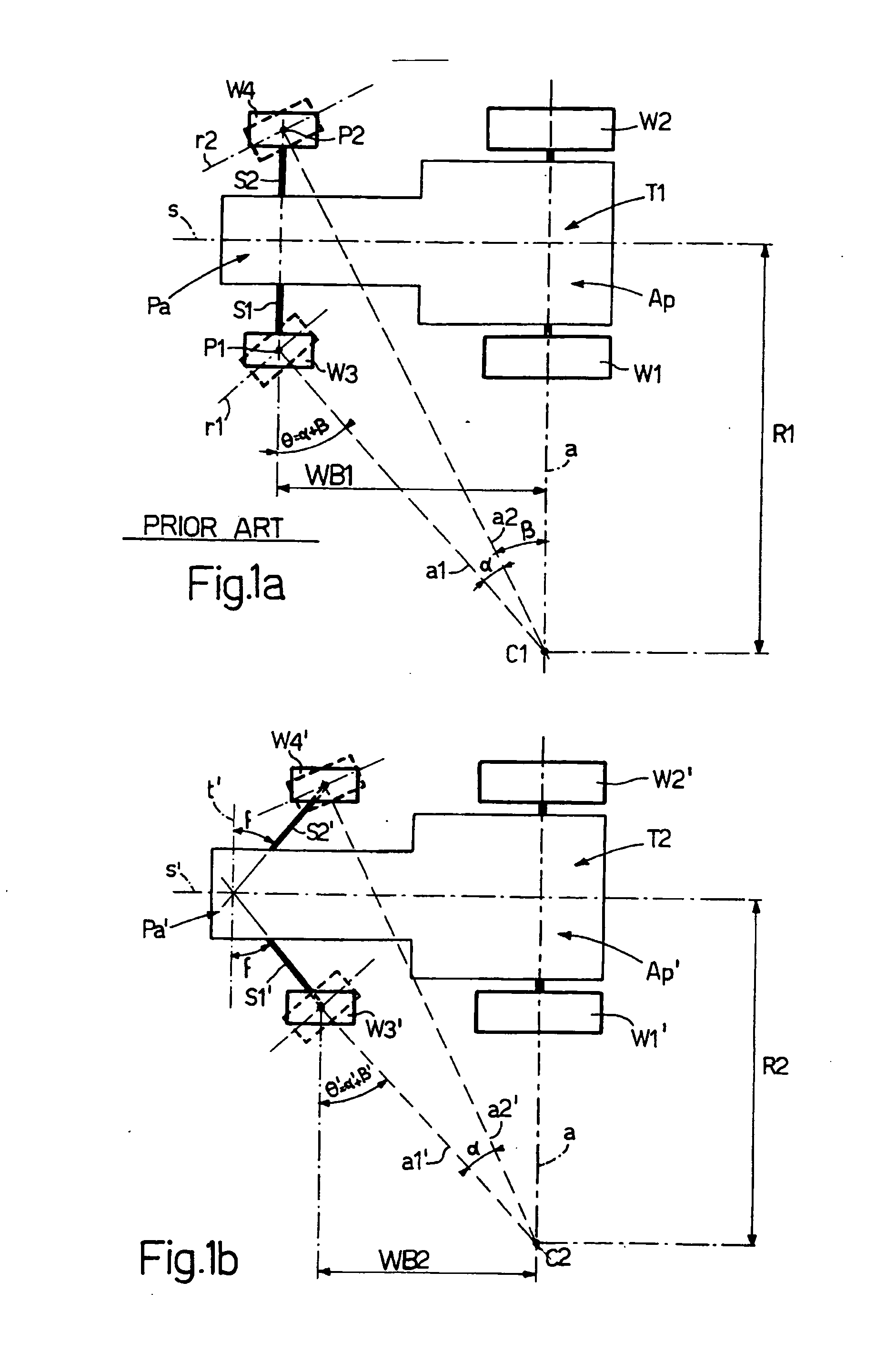
[0026]FIG. 1a shows, schematically, a conventional tractor T1, in which steering is effected by a front axle Pa. The instantaneous turning center C1 of tractor T1 is located along an axis a of a rear axle Ap including two non-directional wheels W1, W2. More specifically, instantaneous turning center C1 is defined as the point at which the projection of rear axis a in the horizontal plane (in other words the plane of the drawing) intersects the projections, in the horizontal plane, of the two horizontal turning axes a1, a2 of the front wheels W3, W4 of front axle Pa. More specifically, axis a1 is perpendicular to the centerline plane r1 of wheel W3, and axis a2 is perpendicular to the centerline plane r2 of wheel W4, when wheels W3, W4 are in their maximum turning position shown in FIG. 1a. In actual fact, front wheel W3 turns about an axis through a point P1 on the centerline within wheel W3, and wheel W4 about an axis through a point P2 on the centerline within wheel W4. Wheels W3,...


PUM


Abstract

A suspended articulated front axle for vehicles, in particular farm tractors, wherein each axle shaft has at least one portion whose longitudinal axis of symmetry slopes by a sweep-back angle with respect to a line perpendicular to the longitudinal axis of symmetry of the vehicle. The sweep-back angle is such that the outer end of the sloping portion is located further back than the inner end of the portion in the common forward traveling direction of the vehicle.

Description

FIELD OF THE INVENTION [0001] The present invention relates to a suspended, articulated and powered front axle for work vehicles, and in particular for tractors. BACKGROUND OF THE INVENTION [0002] In the following description, the front axle is referred to as a “powered front axle.” In many tractors, the front wheels are driven in addition to the rear driven wheels, the tractor having four wheel drive. In many tractors, the front axle is a rigid, transverse structure which is hingeably attached to the front of the tractor chassis for swivelling, transverse movement around the longitudinal middle axis of the tractor. With this axle structure, when one front wheel is raised to overcome an obstacle, the other front wheel has to come down the same distance. Other types of axles are known which, as opposed to being rigid, have articulated end portions, each carrying a front wheel. Each of these end portions includes a deformable system and has a suspension device to transmit part of the ...

Claims


Application Information

Patent Timeline
Patent Type & Authority Applications(United States)
IPC IPC(8): B60G3/18B62D9/00
CPCB60G3/18B60G2200/144B60G2200/422B62D9/00B60G2204/1484B60G2300/082B60G2200/44
Inventor BORDINI, GIORGIO
Owner BORDINI GIORGIO
Why Eureka
Try Eureka