
Media-position sensor system

a sensor system and media technology, applied in the field of hardcopy devices, can solve the problems of increasing the likelihood that a print head may impact against the print media, undulations or wrinkles in the plane of the print media, and the -to-paper spacing, so as to reduce the likelihood of subsequent print defects and other incorrect operations. the effect of significant reduction

Inactive Publication Date: 2005-12-22
HEWLETT PACKARD DEV CO LP
View PDF3 Cites 17 Cited by
  • Summary
  • Abstract
  • Description
  • Claims
  • Application Information

AI Technical Summary

Benefits of technology

The invention provides a printer device that can automatically adjust the distance between the mechanism and the surface where an image is formed, without the need for time-consuming servicing. This mechanism can image a predetermined optical object on the surface and determine the dimension of the object's image, which in turn determines the distance between the mechanism and the surface. This allows for accurate and efficient printing, reducing the likelihood of print defects and other incorrect operation. Additionally, the printer device can allow for adjustment of the separation distance if required, making it user-friendly and convenient. The invention also includes corresponding methods, computer programs, and other aspects that facilitate the use of the invention.

Problems solved by technology

If the spacing to too little, the risk that a print head may impact against the print media increases.
This expansion may cause undulations or wrinkles in the plane of the print media.
If, on the other hand, the pen-to-paper spacing is too great, the ejected dots may not be accurately positioned on the surface of the print medium.
Other artefacts which also degrade print quality may also occur.

Method used


Image

  • Media-position sensor system
  • Media-position sensor system
  • Media-position sensor system

Examples


Embodiment Construction

[0018] In the following detailed description of exemplary embodiments of the invention, reference is made to the accompanying drawings that form a part hereof, and in which is shown by way of illustration specific exemplary embodiments in which the invention may be practiced. These embodiments are described in sufficient detail to enable those skilled in the art to practice the invention. Other embodiments may be utilized, and logical, mechanical, and other changes may be made without departing from the spirit or scope of the present invention. The following detailed description is, therefore, not to be taken in a limiting sense, and the scope of the present invention is defined only by the appended claims.

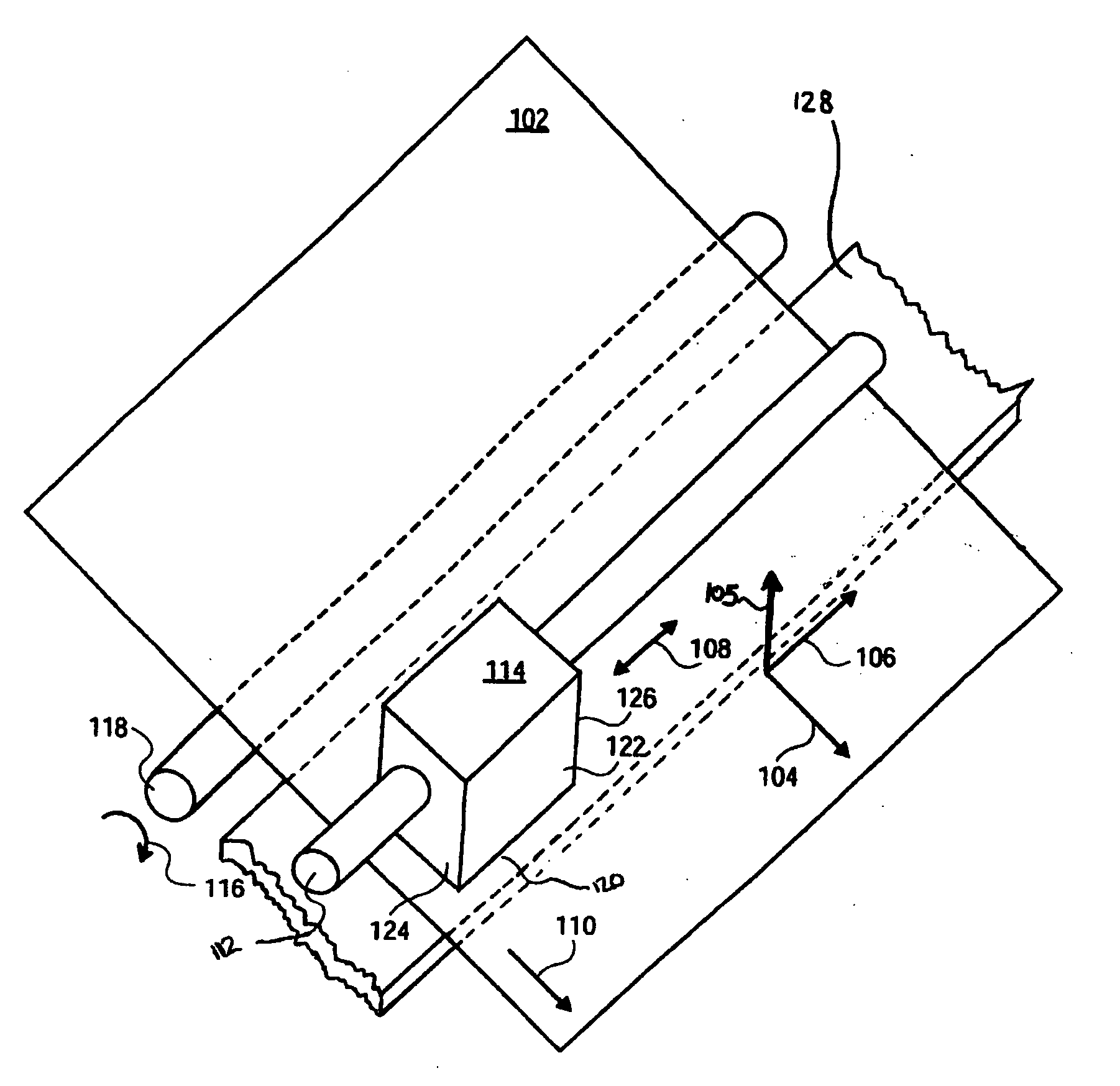
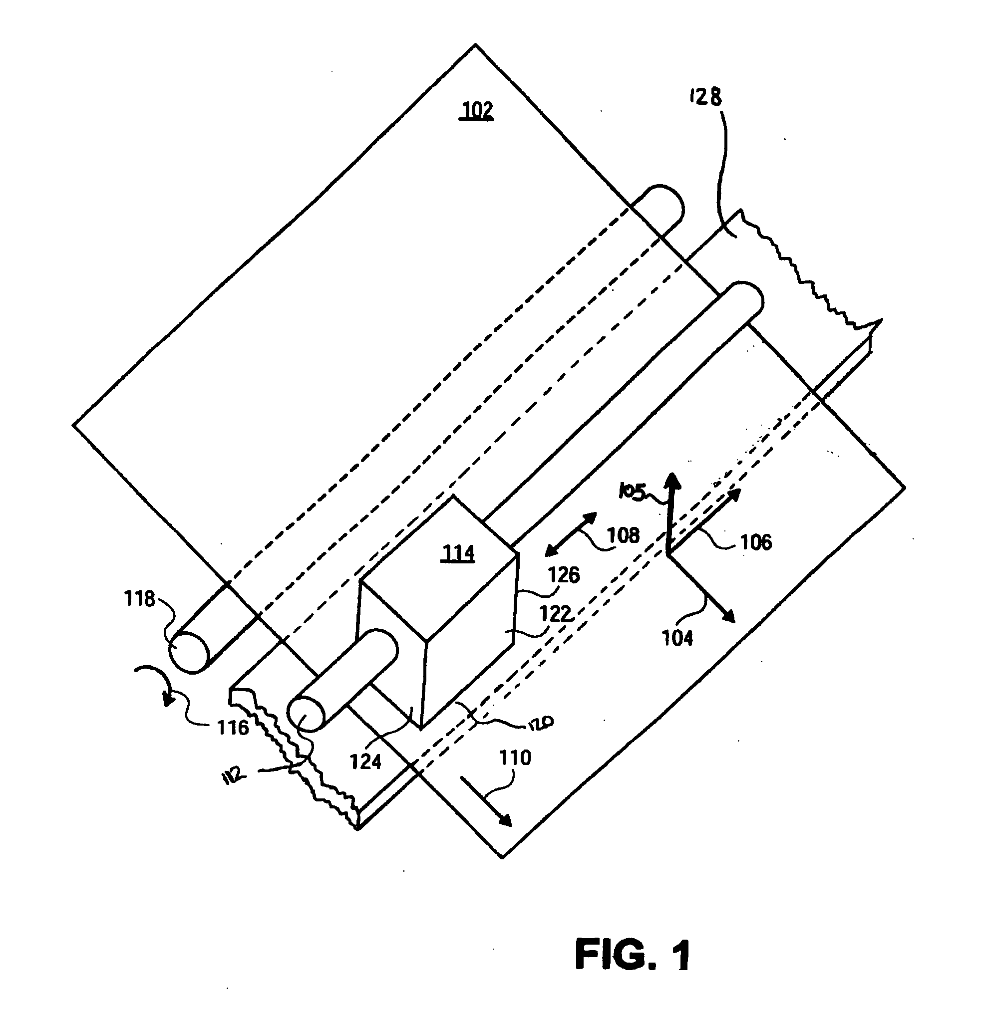
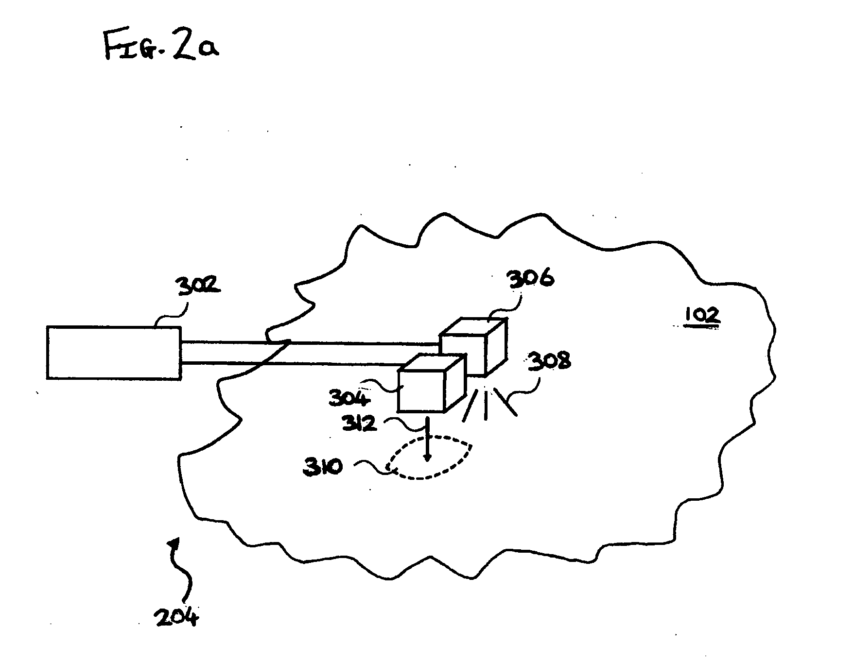
[0019]FIG. 1 shows a perspective view of an image-forming device, according to an embodiment of the invention. The device includes a shaft 112 on which a mechanism, or scanning carriage, 114 is slidably situated. The mechanism 114 has a left side 124, a right side 126, a front 12...


PUM


Abstract

A printer device comprising a mechanism adapted to generate an image on an image surface, the device comprising a sensor adapted to image a predetermined optical object located substantially on the image surface, the device being adapted to determine at least one dimension of the object's image and thereby determine the distance separating the mechanism and the image surface.

Description

FIELD OF THE INVENTION [0001] The present invention relates generally to hardcopy devices, particularly but not exclusively to inkjet printers and to methods of operating such printers. BACKGROUND TO THE INVENTION [0002] As is well known in the art, conventional inkjet printers generally employ one or more inkjet cartridges, often called “pens”, which eject drops of ink onto a page or sheet of print media. The pens are usually mounted on a carriage, which is arranged to scan relative to a sheet of print media as the pens print a series of individual drops of ink on the print media. Often, the pens scan across a scan axis relative to a stationary sheet of print media. The series of drops collectively form a band or “swath” of an image, such as a picture, chart or text. Between scans, the print medium is advanced relative to the scan axis. In this manner, an image may be incrementally printed. In other arrangements, the pens, in the form of a page wide array for example, may remain st...

Claims


Application Information

Patent Timeline
Patent Type & Authority Applications(United States)
IPC IPC(8): B41J11/00
CPCB41J11/0095B41J11/0035
Inventor FLOTATS, CARLESCLARAMUNT, DAVIDRIO DOVAL, JOSE M.RUIZ, RODRIGOSUBIRADA, FRANCESC
Owner HEWLETT PACKARD DEV CO LP
Learn More