Ultraviolet light-emitting diode device

a light-emitting diode and ultra-violet technology, applied in semiconductor devices, display means, printing, etc., can solve the problems of increasing the difficulty and cost of curing uv curable fluid, increasing size and cost, and reducing the number of light-emitting sources, so as to reduce the size and cost of uv led devices, the effect of reducing the amount of time required

Inactive Publication Date: 2005-12-22
SUMMIT BUSINESS PRODS
View PDF25 Cites 43 Cited by
  • Summary
  • Abstract
  • Description
  • Claims
  • Application Information

AI Technical Summary

Benefits of technology

[0006] The present invention relates to light-emitting diode devices. More particularly, the present invention relates to an ultraviolet (UV) light-emitting diode (LED) device for curing fluids such as inks, coatings, and adhesives, for example. In one embodiment, LEDs are positioned on faces defined by an inverted recess in a base portion. The LEDs are configured such that the light beams emitted from the LEDs converge at a single area or point to provide a single, focused area or point of amplified power from the LEDs. In another embodiment, the base portion is elongated to provide a single, focused line or region of amplified power from the LEDs. In one embodiment, the curing process occurs in an inert atmosphere. Because of the reduced number of light emitting sources required by the present invention, the size and cost of the UV LED device may advantageously be decreased. In one embodiment, a printed circuit is disposed in the base portion to provide power to the LEDs. All of the embodiments of the present invention advantageously reduce the amount of time required for curing the fluid and increase the efficiency of the curing process.

Problems solved by technology

However, these methods are often time-consuming and inefficient, thereby increasing difficulty and expense for curing UV curable fluids.
For example, known UV LED fluid-curing devices require a large number of light emitting sources which not only add size and cost to a fluid-curing device, but also are inefficient in terms of power usage.

Method used


Image

  • Ultraviolet light-emitting diode device
  • Ultraviolet light-emitting diode device
  • Ultraviolet light-emitting diode device

Examples


Embodiment Construction

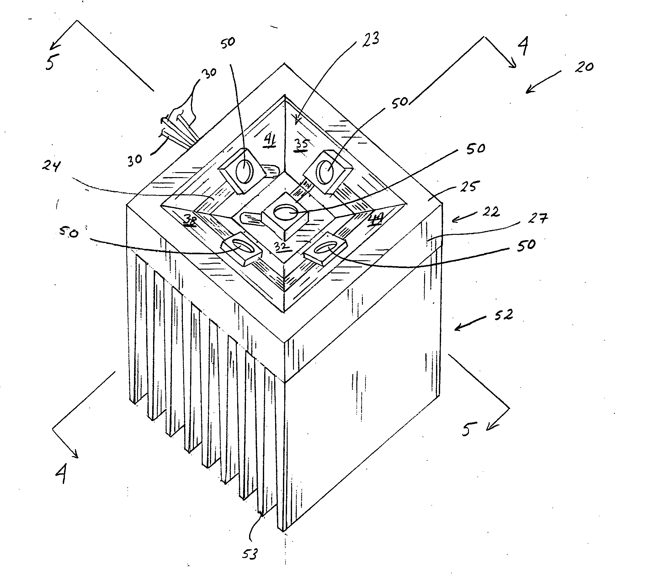
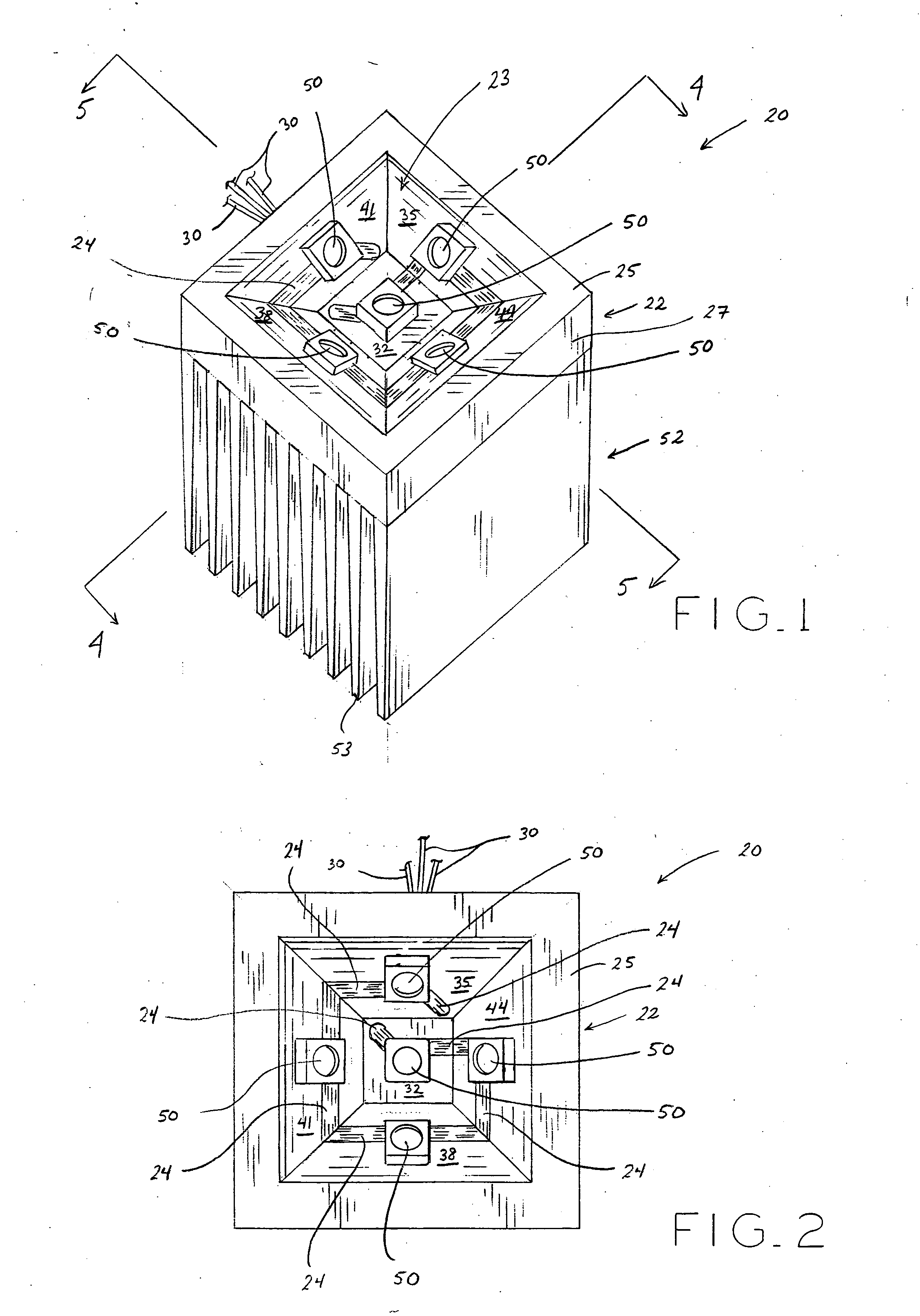
[0024] The present invention generally provides LED devices. More particularly, the present invention relates to a UV LED device for curing fluids. In one embodiment, LEDs are positioned on faces defined by an inverted recess in a base portion. The LEDs are configured such that the light beams emitted from the LEDs converge at a single area or point to provide a single, focused area or point of amplified power from the LEDs. In another embodiment, the base portion is elongated to provide a single, focused line or region of amplified power from the LEDs. In one embodiment, the curing process occurs in an inert atmosphere. Advantageously, all of the embodiments of the present invention reduce the amount of time required for curing the fluids and increase the efficiency of the curing process because of the focused configuration of the plurality of LEDs.

[0025] Referring to FIGS. 1 and 11, LED device base 22 is shown including bottom edge 25 and recess 23 including faces 32, 35, 38, 41,...


PUM


Abstract

A UV LED device may be used for curing fluids. In one embodiment, LEDs are positioned on faces defined by an inverted recess in a base portion. The LEDs are configured such that the light beams emitted from the LEDs converge at a single area or point to provide a single, focused area or point of amplified power from the LEDs. In another embodiment, the base portion is elongated to provide a single, focused line or region of amplified power from the LEDs. In another embodiment, the curing process occurs in an inert atmosphere. In one embodiment, a printed circuit is disposed in the base portion to provide power to the LEDs.

Description

BACKGROUND [0001] 1. Field of the Invention [0002] The present invention relates to light-emitting diode devices and, more particularly, to ultraviolet light-emitting diode devices for use in curing fluids. [0003] 2. Description of the Prior Art [0004] In methods for ultraviolet (UV) curing of fluids including inks, coatings, and adhesives, the cured substance includes UV photo initiators therein which, when exposed to UV light, convert monomers in the fluids into linking polymers to solidify the monomer material. Conventional methods for UV curing employ UV light-emitting diodes (LEDs) and UV lamps to supply UV light for curing UV curable fluids on various products. However, these methods are often time-consuming and inefficient, thereby increasing difficulty and expense for curing UV curable fluids. For example, known UV LED fluid-curing devices require a large number of light emitting sources which not only add size and cost to a fluid-curing device, but also are inefficient in t...

Claims


Application Information

Patent Timeline
Patent Type & Authority Applications(United States)
IPC IPC(8): B41J2/01B41J11/00H01L33/00H01L33/48
CPCB41J11/002Y10S362/80B41J11/00218B41J11/00214
Inventor CUSTER, ERIC J.
Owner SUMMIT BUSINESS PRODS
Why Eureka
Try Eureka