Imaging apparatus

a technology of imaging apparatus and spherical tube, which is applied in the direction of color television details, television system details, television systems, etc., to achieve the effect of high image quality

Inactive Publication Date: 2005-12-22
HITACHI LTD
View PDF26 Cites 30 Cited by
  • Summary
  • Abstract
  • Description
  • Claims
  • Application Information

AI Technical Summary

Benefits of technology

[0008] This invention can realize an imaging apparatus having a plurality of imaging means which can achieve a high image quality.

Problems solved by technology

This problem often becomes conspicuous especially in the case where the subject moves quickly and the exposure time is often shortened using the electronic shutter (or the mechanical shutter) function to suppress the blur or the out-of-focus state caused by the movement of the subject.

Method used


Image

  • Imaging apparatus
  • Imaging apparatus
  • Imaging apparatus

Examples


first embodiment

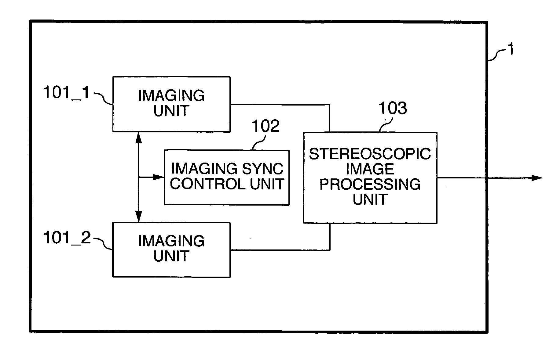
[0016]FIG. 1 is a schematic diagram showing a stereoscopic imaging system according to a first embodiment of the invention. In FIG. 1, reference numeral 1 designates a stereoscopic imaging apparatus, numeral 101_1 a first imaging unit, numeral 101_2 a second imaging unit, numeral 102 an imaging sync control unit, and numeral 103 a stereoscopic image processing unit.

[0017] In the stereoscopic imaging apparatus 1, the first imaging unit 101_1 picks up an image and outputs a video signal. The second imaging unit 101_2 similarly picks up an image and outputs a video signal. The imaging sync control unit 102 controls the imaging synchronism between the first imaging unit 101_1 and the second imaging unit 101_2. The stereoscopic image processing unit 103 processes the images picked up stereoscopically by executing the process of extracting / recognizing the subject and calculating the distance to and the position of the subject based on triangulation using the video signals output from the...

second embodiment

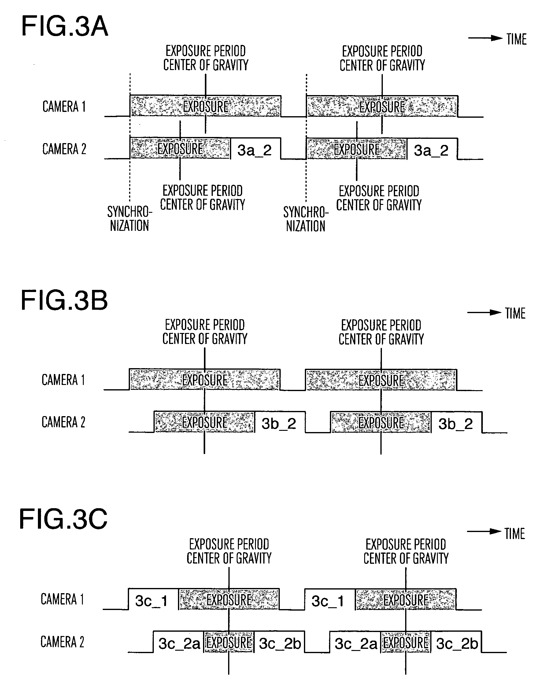
[0023]FIGS. 3A to 3C are diagrams showing an example of the exposure control timing of the stereoscopic imaging system according to a second embodiment of the invention. In FIG. 3A, the camera 2 controls the exposure using a mechanical shutter, and so does the camera 2 in FIG. 3B. In FIG. 3C, on the other hand, the camera 1 controls the exposure using the electronic shutter function, while the camera 2 controls the exposure using both the electronic shutter function and the mechanical shutter function. The camera 1 is equivalent to the first imaging unit 101_1 shown in FIG. 1, and the camera 2 to the second imaging unit 101_2 shown in FIG. 1.

[0024] In the case where the exposure is controlled using the mechanical shutter in the stereoscopic imaging system, the synchronization of the imaging timing among a plurality of cameras leads to different timings of the center of gravity of the exposure period among the cameras as shown in 3a of FIG. 3, thereby posing the problem of a reduced...

third embodiment

[0028]FIGS. 4A and 4B are diagrams showing an example of the exposure control timing of a stereoscopic imaging system according to a third embodiment of the invention. In FIGS. 4A and 4B, the camera 1 and the camera 2 have different imaging periods. The camera 1 is equivalent to the first imaging unit 101_1 shown in FIG. 1, and the camera 2 to the second imaging unit 101_2 shown in FIG. 1.

[0029] In this stereoscopic imaging system, the synchronization of the imaging timing among the cameras having different imaging periods leads to different timings of the center of gravity of the exposure period among the cameras as shown in FIG. 4A, thereby posing the problem of a reduced image processing capability of the stereoscopic imaging operation. According to this embodiment, as shown in FIG. 4B, the phase of the imaging timing is displaced among a plurality of cameras, and therefore the respective cameras are set to the same timing of the center of gravity of the exposure period.

[0030] ...


PUM


Abstract

A stereoscopic imaging system includes a stereoscopic imaging apparatus having a plurality of imaging modules to pick up an image and an imaging sync control module to arithmetically process the video signals output from the plurality of the imaging modules for the stereoscopic imaging operation. In the case where the imaging modules control the exposure using an electronic shutter function and come to have different timing of the center of gravity of the exposure period, an imaging sync control module sets the plurality of the imaging modules at the same timing of the center of gravity of the exposure period by displacing the phase of the timing of the center of gravity of the exposure period of the imaging modules thereby to prevent the image processing capability of the stereoscopic imaging operation from being reduced.

Description

INCORPORATION BY REFERENCE [0001] The present application claims priority from Japanese application JP 2004-179143 filed on Jun. 17, 2004, the content of which is hereby incorporated by reference into this application. BACKGROUND OF THE INVENTION [0002] The present invention relates to an imaging apparatus having a plurality of imaging means. [0003] An example of the background art in this technical field is disclosed in JP-A-2002-145072. The subject of this publication is “to provide a railway crossing obstacle detection apparatus capable of detecting an obstacle with high accuracy over a wide range within the crossing” and as a solution, the publication discloses a technique relating to “a railway crossing obstacle detection apparatus comprising at least a pair of left and right cameras 11a, 11b arranged directed to the monitor area within a crossing to acquire the left and right images of the monitor area, and execute the process including a first stage to extract a change portio...

Claims


Application Information

Patent Timeline
Patent Type & Authority Applications(United States)
IPC IPC(8): H04N5/225H04N5/235H04N5/335H04N5/341H04N5/353H04N13/00H04N13/02H04N15/00
CPCH04N13/0296H04N13/0239H04N13/239H04N13/296
Inventor NAKANO, NORIHIKOUSUI, TSUTOMUSAI, HIROTOMO
Owner HITACHI LTD
Why Eureka
Try Eureka