Control circuit

a control circuit and circuit technology, applied in the direction of emergency protective arrangements for limiting excess voltage/current, electrical equipment, etc., can solve the problems of dc current harming the inductor or semiconducting elements in the circuit, and the current increases rapidly, so as to reduce the harm of a trapped current

Inactive Publication Date: 2005-12-22
ABB POWER GRIDS SWITZERLAND AG +1
View PDF6 Cites 12 Cited by
  • Summary
  • Abstract
  • Description
  • Claims
  • Application Information

AI Technical Summary

Benefits of technology

[0007] A primary object of the present invention is to provide a protecting device for a control circuit by which the harmful effect of a trapped current is reduced. A secondary object of the invention is to protect elements in a control circuit containing an inductor in an electric power transmission system.

Problems solved by technology

Even though the bypass is achieved within a quarter of a period there might be situations when the current increases rapidly within that quarter of a period.
This dc current will harm the inductor or the semiconducting elements in the circuit.

Method used


Image

  • Control circuit
  • Control circuit
  • Control circuit

Examples


Embodiment Construction

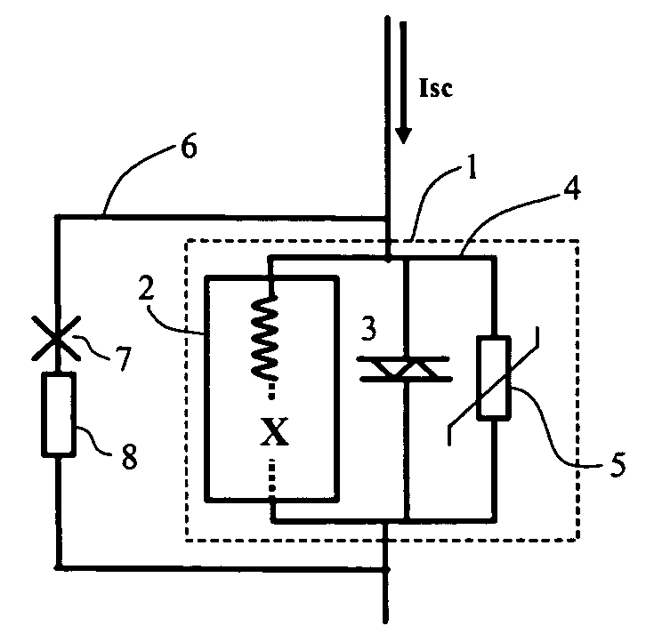
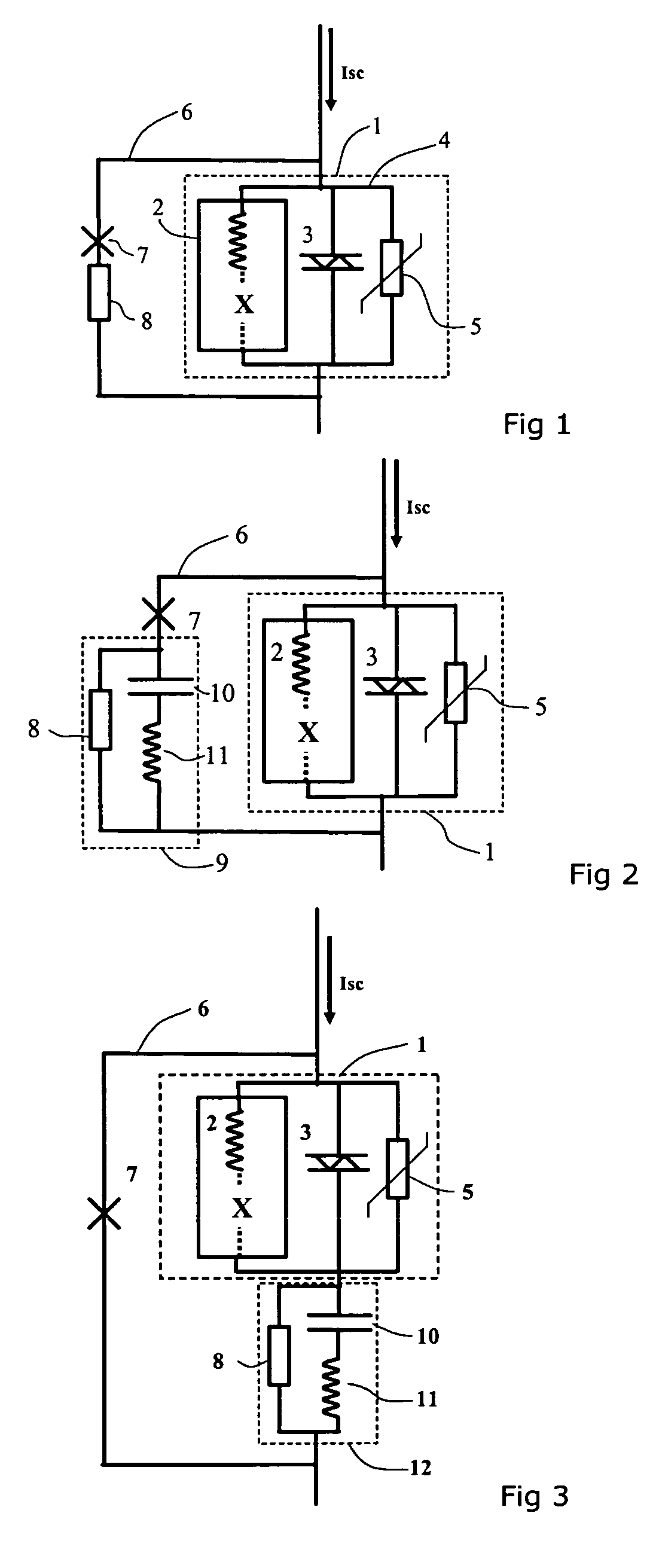
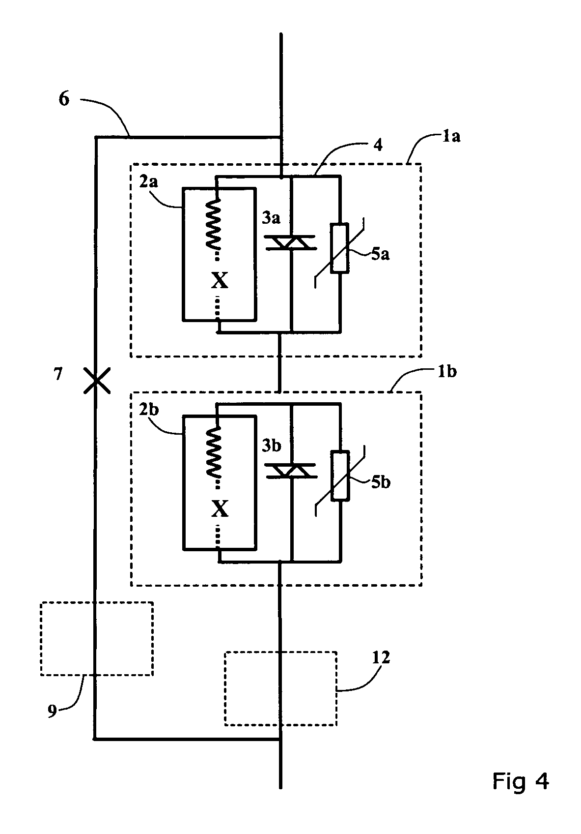
[0023] A device including a control circuit 1 for controlling the power flow in a electric power transmission line is shown in FIG. 1. The control circuit comprises an inductor 2 in parallel connection with a semiconducting element 3. In the embodiment the semiconducting element comprises a bidirectional thyristor or an arrangement of two antiparallel thyristors. By controlling the thyristor the current flowing through the circuit is either passing through the inductor or bypassed by the thyristor. The control circuit further comprises a first bypass path 4 containing a surge arrester 5 for overvoltage protection. The control circuit is protected from overcurrents by a second bypass path 6 comprising a closing switch 7.

[0024] In circuits like the one showed in FIG. 1, containing inductance and where it is required to bypass the circuit for protection at short circuit current (Isc), a trapped current may occur. When a bypass is created by a device without current interrupting capabi...


PUM


Abstract

A device for controlling a power flow in an electric power transmission system. A control circuit includes a first inductor and a semiconducting switching element connected in parallel with the first inductor. The control circuit also includes a first bypass path including a surge arrester. A second bypass path is connected in parallel with the control circuit. The second bypass path includes a closing switch. The device also includes a resistor.

Description

TECHNICAL FIELD [0001] The present invention concerns a device and a method for controlling the power flow in an electric transmission line. More precisely the invention concerns a method and an apparatus for protection of a control circuit of a transmission line. The circuit comprises at least one unit containing a inductor and a semiconducting element. A semiconducting element in this context should be broadly understood to include all devices that has semiconducting properties and thus comprising diodes as well as semiconducting switching element such as a thyristor or an IGBT. An inductor in this context should be understood to comprise one or a plurality of units that comprises inductive properties. An inductor thus also includes a combination of elements, some of them having semiconducting properties, which form a unit that exhibit inductive properties. BACKGROUND OF THE INVENTION [0002] Circuit for controlling the power flow of an electric power transmission system often invo...

Claims


Application Information

Patent Timeline
Patent Type & Authority Applications(United States)
IPC IPC(8): H02H9/00
CPCH02H9/002H02H9/02
Inventor JONSSON, TOMAS
Owner ABB POWER GRIDS SWITZERLAND AG
Why Eureka
Try Eureka