Electric mixer

Inactive Publication Date: 2005-12-22
LEE YEONG IND
View PDF6 Cites 16 Cited by
  • Summary
  • Abstract
  • Description
  • Claims
  • Application Information

AI Technical Summary

Benefits of technology

[0009] According to the above object, the electric mixer includes a driving mechanism and a transmission mechanism positioned under the driving mechanism for outputting the power of the driving mechanism and controlling rotational direction of mixing rods and paddles disposed at the ends of the mixing rods. The mixing rods and paddles are mounted under the transmission mechanism. A first connecting tube, a second connecting tube and a third connecting tube are parallelly arranged under bottom face of the transmission mechanism at intervals. The first

Problems solved by technology

The above single-paddle mixer is operated at lower speed and can hardly fully mix the materials.
With such fixed assembly, when necessary, it is impossible to switch th

Method used


Image

  • Electric mixer
  • Electric mixer
  • Electric mixer

Examples


Example

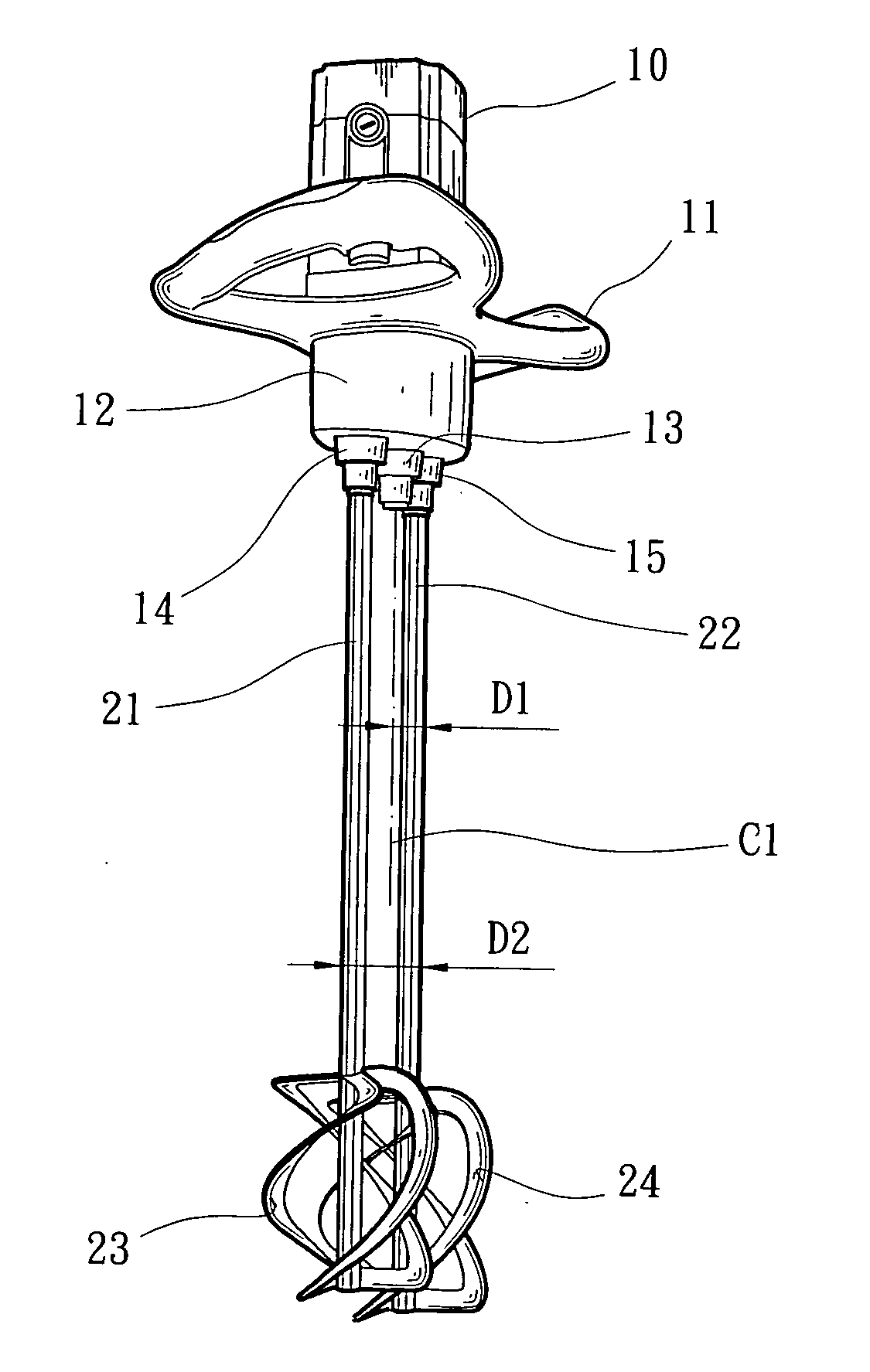
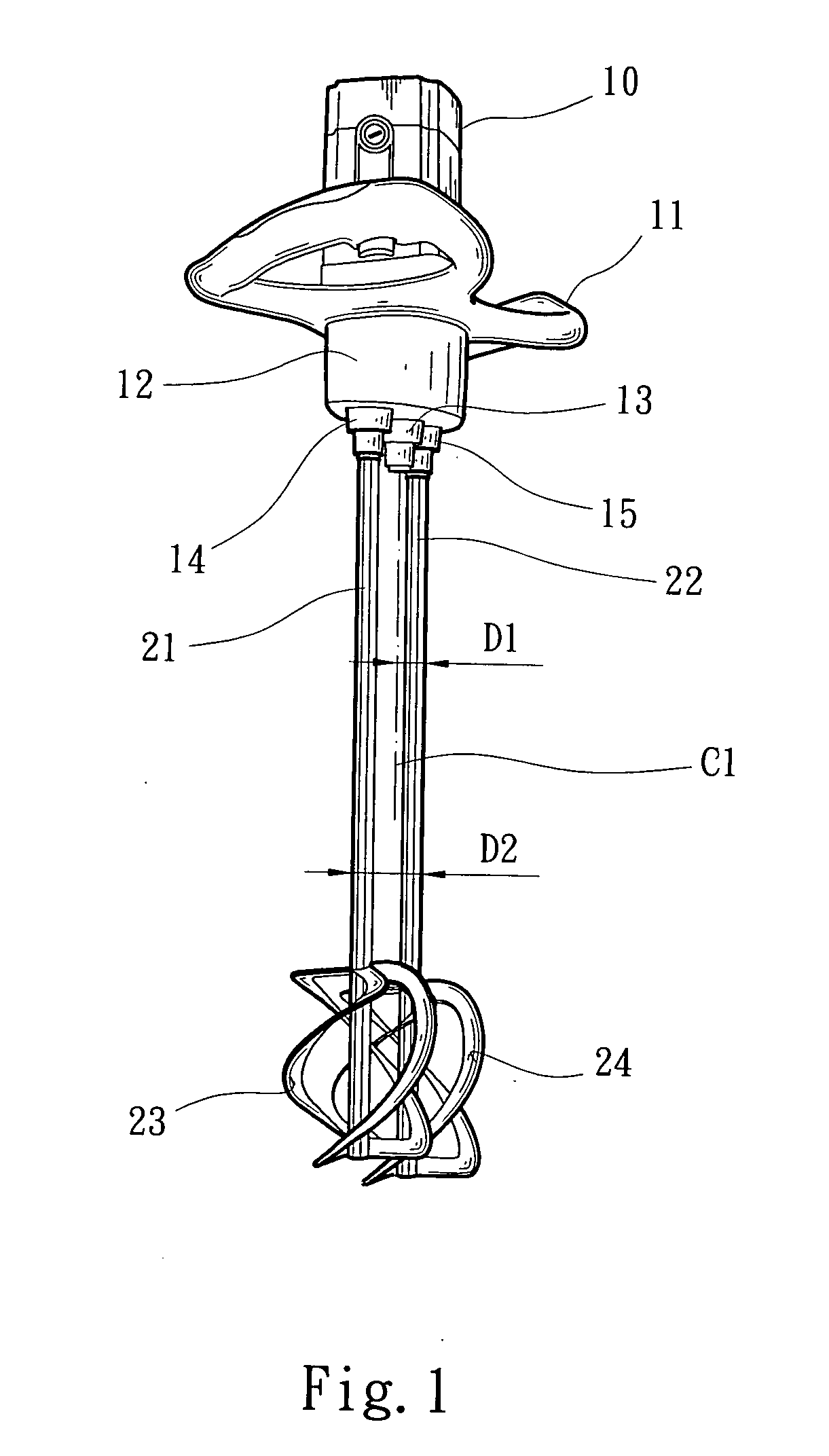
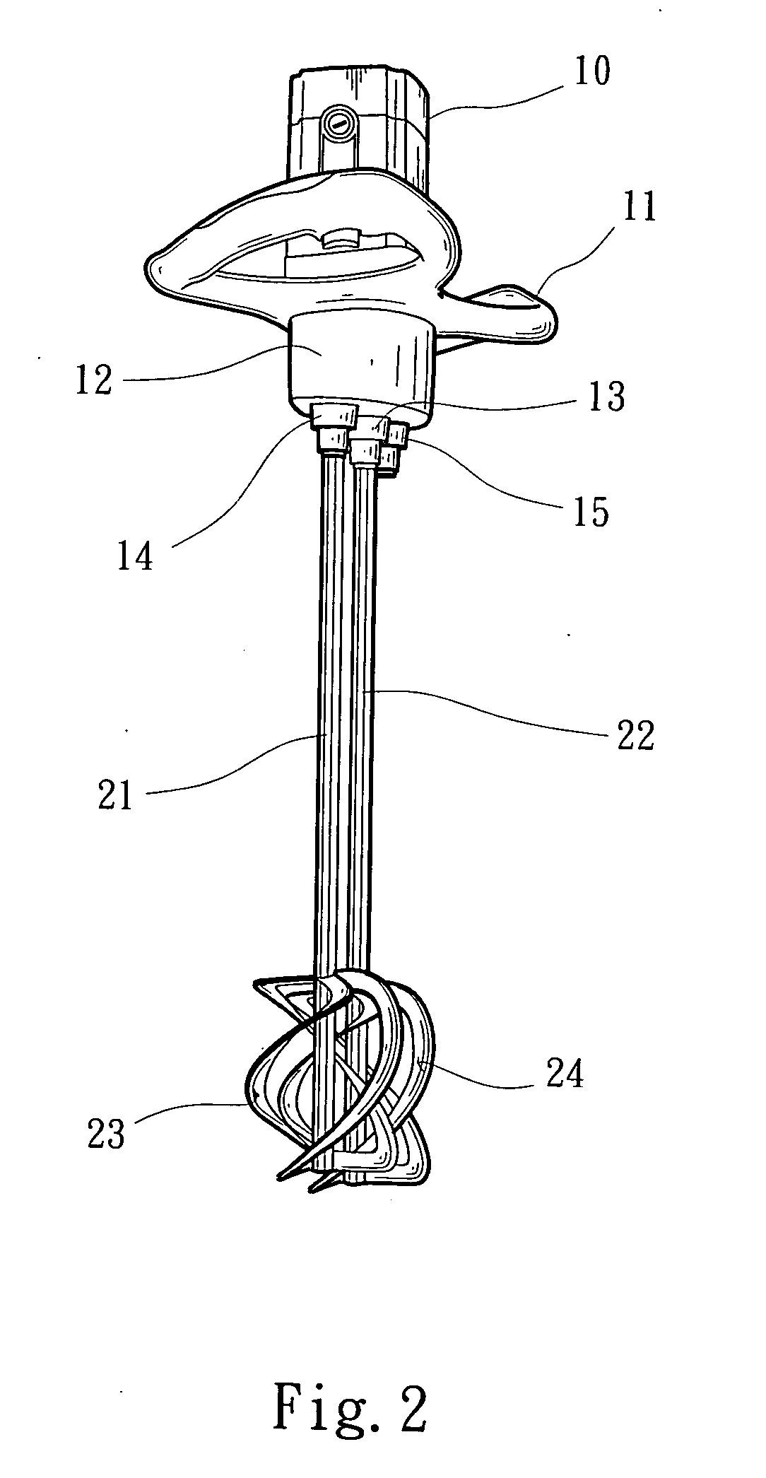
[0014] Please refer to FIG. 1. The electric mixer of the present invention includes a driving mechanism 10 and relevant units (such as locating board 11) disposed at top end of the mixer. The electric mixer further includes a transmission mechanism 12 positioned under the driving mechanism 10 for outputting the power of the driving mechanism 10 and controlling the rotational direction of the mixing rods and paddles disposed at the ends of the mixing rods. The mixing rods and paddles are mounted under the transmission mechanism 12. With a twin-paddle electric mixer exemplified, one paddle is controlled to forward rotate, while another paddle is controlled to backward rotate.

[0015] A first connecting tube 13, a second connecting tube 14 and a third connecting tube 15 are parallelly arranged under bottom face of the transmission mechanism 12 at intervals. The first connecting tube 13 is positioned in the middle, while the second and third connecting tubes 14, 15 are respectively dispo...


PUM


Abstract

An electric mixer including a driving mechanism and a transmission mechanism. A first connecting tube, a second connecting tube and a third connecting tube which are parallelly arranged under the transmission mechanism at intervals. The first connecting tube is positioned in the middle of the electric mixer for connecting with and driving a mixing rod and a paddle. The second and third connecting tubes are respectively disposed on two sides of the first connecting tube. Each of the second and third connecting tubes serves to connect with and drive another mixing rod and another paddle. A smaller first gap is defined between the first middle connecting tube and any of the second and third lateral connecting tubes. A larger second gap is defined between the second and third connecting tubes. One mixing rod and paddle thereof can be connected with any of the first, second and third connecting tubes to form a single-paddle electric mixer. Alternatively, two mixing rods and paddles thereof can be respectively connected with the second and third connecting tubes to form a twin-paddle electric mixer with the larger gap. Still alternatively, two mixing rods and paddles thereof can be respectively connected with the first middle connecting tube and any of the second and third connecting tubes to form a twin-paddle electric mixer with the smaller gap.

Description

BACKGROUND OF THE INVENTION [0001] The present invention is related to an electric mixer. One or two mixing rods and paddles thereof can be assembled to form a single-paddle electric mixer or a twin-paddle electric mixer. In addition, the two mixing rods and paddles thereof can be selectively disposed in different positions, whereby the gap between the mixing rods and paddles is changeable for achieving different mixing strengths. [0002] Some materials such as paints and waterproof paints generally need to be blended with other materials before painting. Also, some chemical materials must be mixed with each other in a set ratio. Therefore, a mixer is necessary for mixing these materials. An electric mixer is able to quickly and conveniently mix the materials. [0003] An earlier electric mixer has one single mixing rod driven by a motor. One paddle is connected with a rear end of the mixing rod for extending into the materials to blend the same. [0004] The above single-paddle mixer is...

Claims


Application Information

Patent Timeline
IPC IPC(8): B01F7/00B01F13/00B01F15/00
CPCB01F7/00583B01F7/00725B01F2215/0047B01F13/002B01F7/00975B01F27/13B01F27/213B01F27/2322B01F33/5011B01F2101/28
Inventor HSIEH, PAN-CHUNG
Owner LEE YEONG IND
Why Eureka
Try Eureka