Transmission having plural clutches
- Summary
- Abstract
- Description
- Claims
- Application Information
AI Technical Summary
Benefits of technology
Problems solved by technology
Method used
Image

Examples
first embodiment
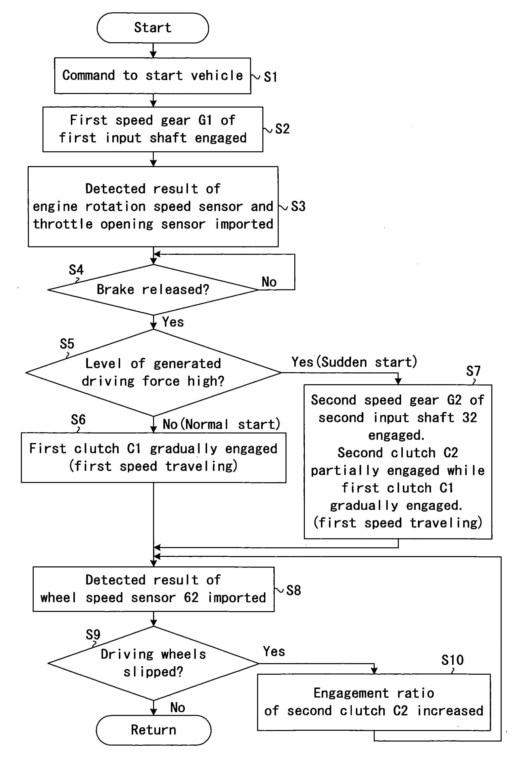
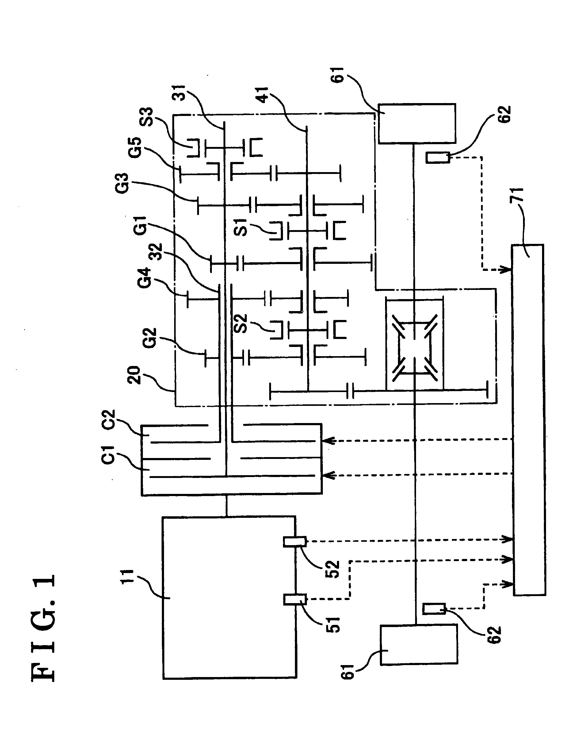
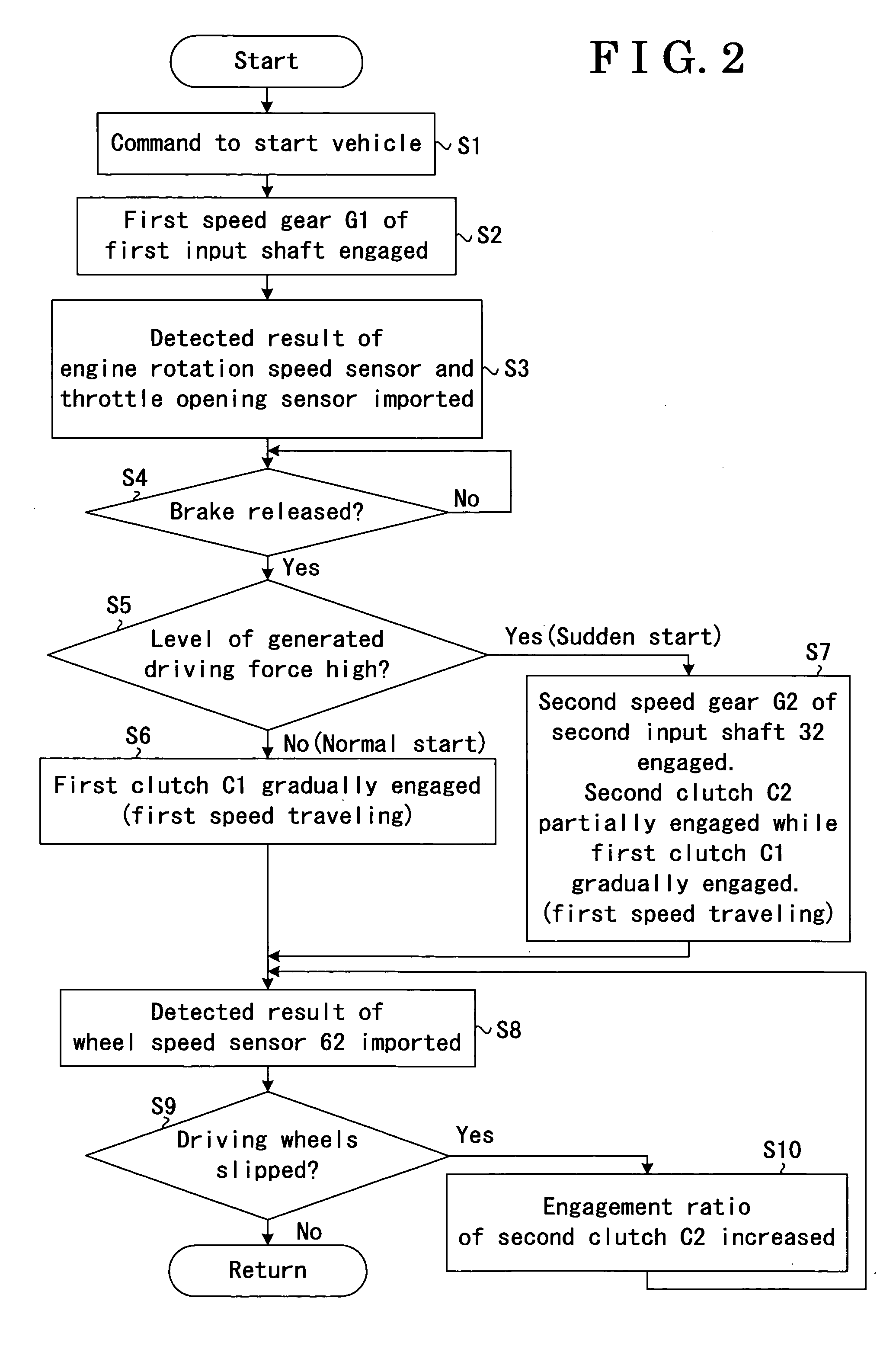
[0015] Embodiments of the present invention will be explained with reference to illustrations of drawing figures as follows. the present invention will be explained referring to FIG. 1. Dotted arrows in FIG. 1 show flows of detection signals and control. A transmission having plural clutches includes a first clutch C1, a second clutch C2, a first input shaft 31, a second input shaft 32, an engine rotation speed sensor 51 serving as a driving force detection means, a throttle opening sensor 52 serving as the driving force detection means, a wheel speed sensor 62 serving as a slip detection means, and a driving portion control device 71 serving as a means for controlling a second clutch.
[0016] The first clutch C1 transmits rotational driving force of an engine 11 serving as a driving force generating means by connecting the first input shaft 31 of an automatic transmission 20 driven by the engine 11, and does not transmit the rotational driving force of the engine 11 by disconnecting ...
second embodiment
[0027] A second embodiment of the present invention is explained with reference to FIG. 4, as follows. According to the present invention, a first input shaft 131 of a transmission 121 includes driving gears G1-G5 for five-speed, and a second input shaft 132 includes a driving force reduction gear GX. Gear ratio of the driving force reduction gear GX is different from any one of driving gears of the first input shaft, and the driving force reduction gear GX is always geared with a driven gear of the output shaft 141. A driving force transmitting path from the second clutch C2 to the output shaft 141 via the second input shaft 132 and the driving force reduction gear GX is not used for the actual vehicle traveling, and converts a part of the driving force to the thermal energy. With this construction, by means of the control and operation likewise the first embodiment of the present invention, the slip of the driving wheel can be restrained.
[0028] With the construction of the transmi...
PUM
 Abstract
Description
Claims
Application Information