Monitoring system for induction sealer

a technology of induction sealer and monitoring system, which is applied in the direction of caps, liquid handling, transportation and packaging, etc., can solve the problems of affecting the cost of the manufacturer, the product is returned to the manufacturer, and the hermetic seal may be incorrectly formed, labor-intensive and costly,

Active Publication Date: 2005-12-29
AUTO KAPS
View PDF13 Cites 21 Cited by
  • Summary
  • Abstract
  • Description
  • Claims
  • Application Information

AI Technical Summary

Benefits of technology

[0020] According to another aspect of the present invention, the monitoring system may include a power sensor for monitoring the power consumed by the induction head. In the preferred embodiment of the invention, the power sensor is a current sensor that detects the current supplied to the induction head, the detected current being proportional to the power supplied to the induction head. According to one aspect of the invention, the controller uses the detected current from the current detector to visually display through the display system a representation of the power supplied to the induction head. In this way, a system operator can visually monitor the power consumption of the induction head and can take appropriate action when the power drawn gets close to the maximum power allowed under a selected power setting.

Problems solved by technology

For example, when the content of a container is medicine, a misapplied foil 106 may cause a consumer to suspect product tampering, thereby returning the product to the manufacturer and affecting manufacturer costs.
Similarly, a hermetic seal may be incorrectly formed as a result of the bottle being under or over heated, for example.
However, this is labor intensive and costly and it may be difficult for an operator to even detect a problem when it occurs.
In addition, because the sealing operation is a mechanical and automated process, system failures can occur.
For example, bottles can stall under the induction head due to a conveyor belt stopping or bottles jamming and as a result, become overheated.
Similarly, the system may overheat.
Again, a system operator can constantly oversee the sealing operation, but this is costly.

Method used


Image

  • Monitoring system for induction sealer
  • Monitoring system for induction sealer
  • Monitoring system for induction sealer

Examples


Embodiment Construction

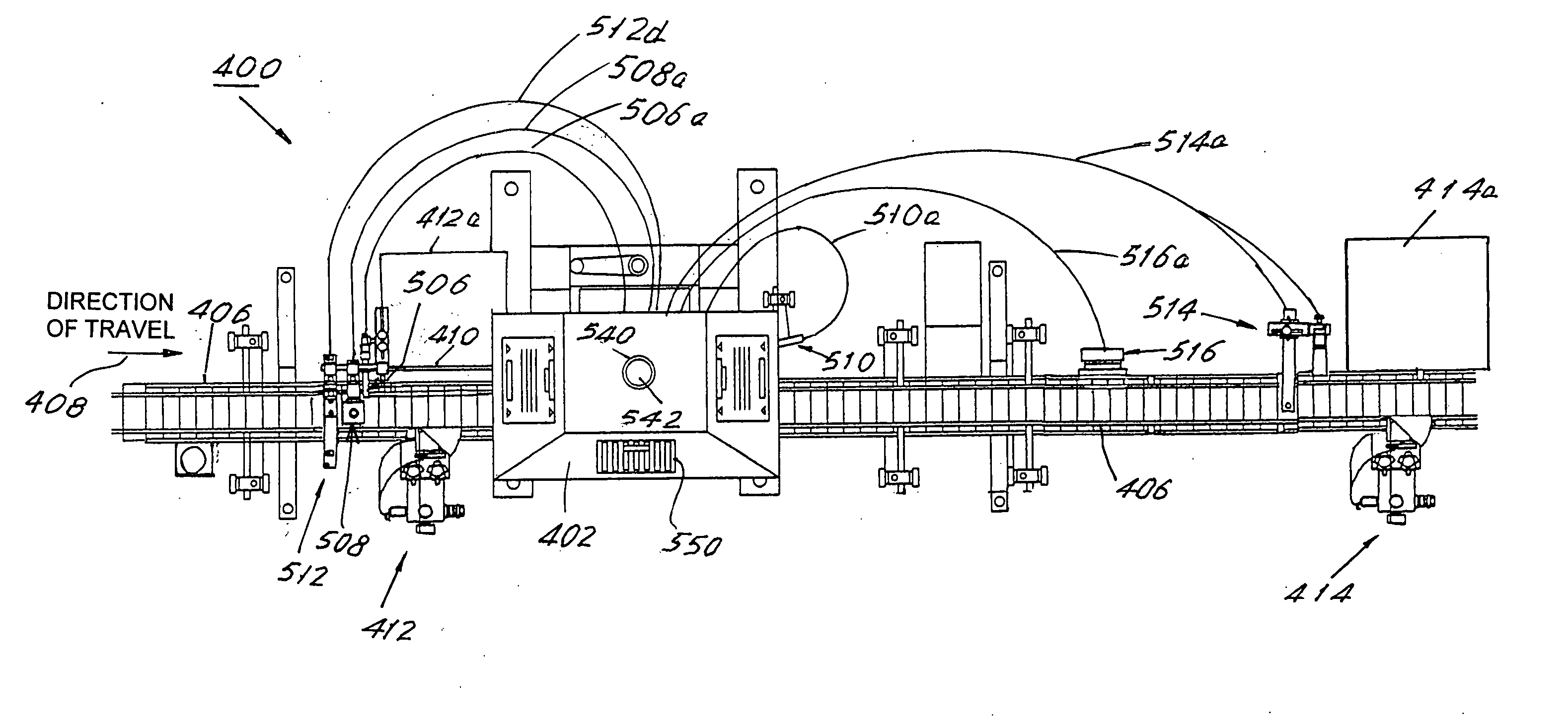
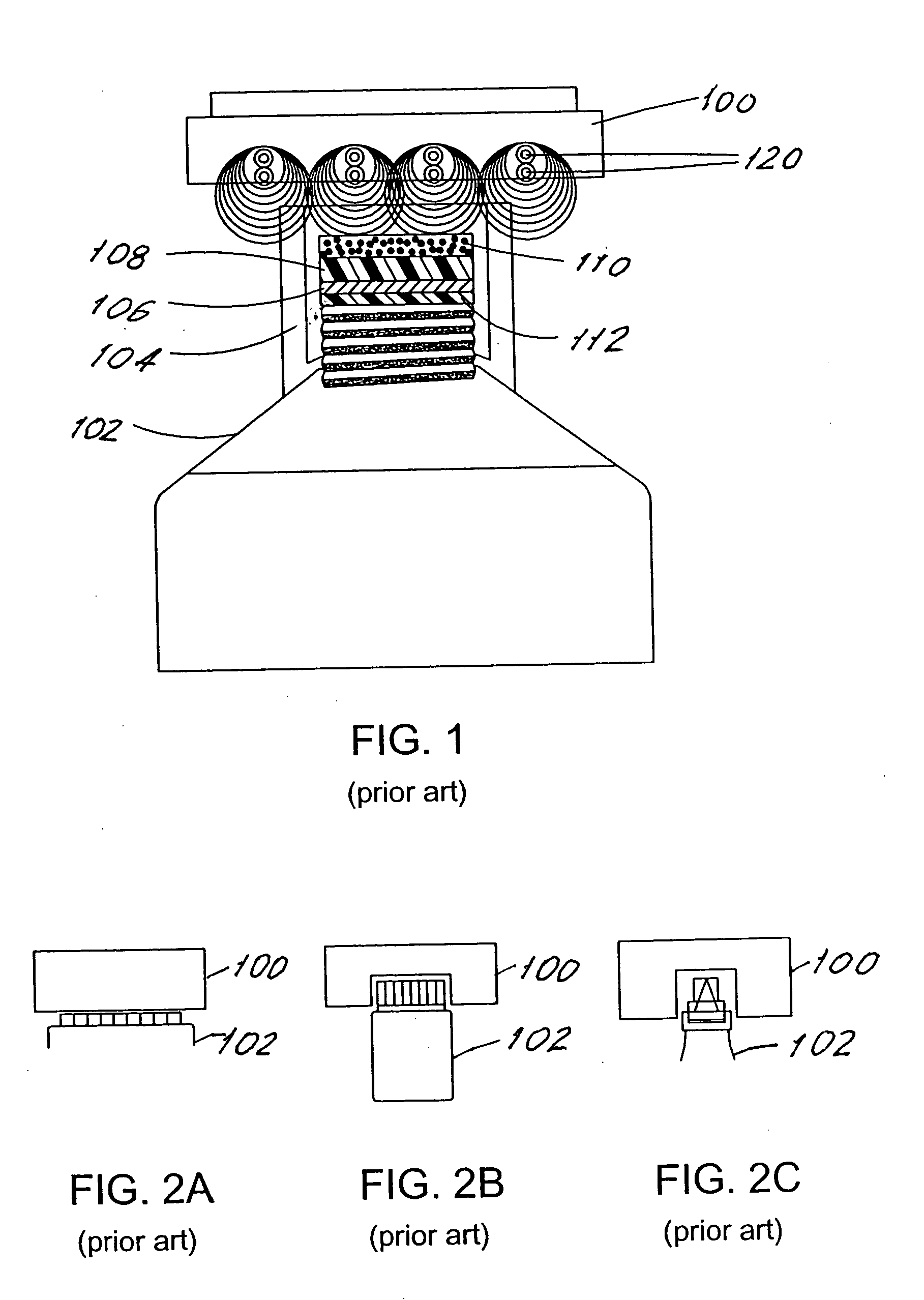
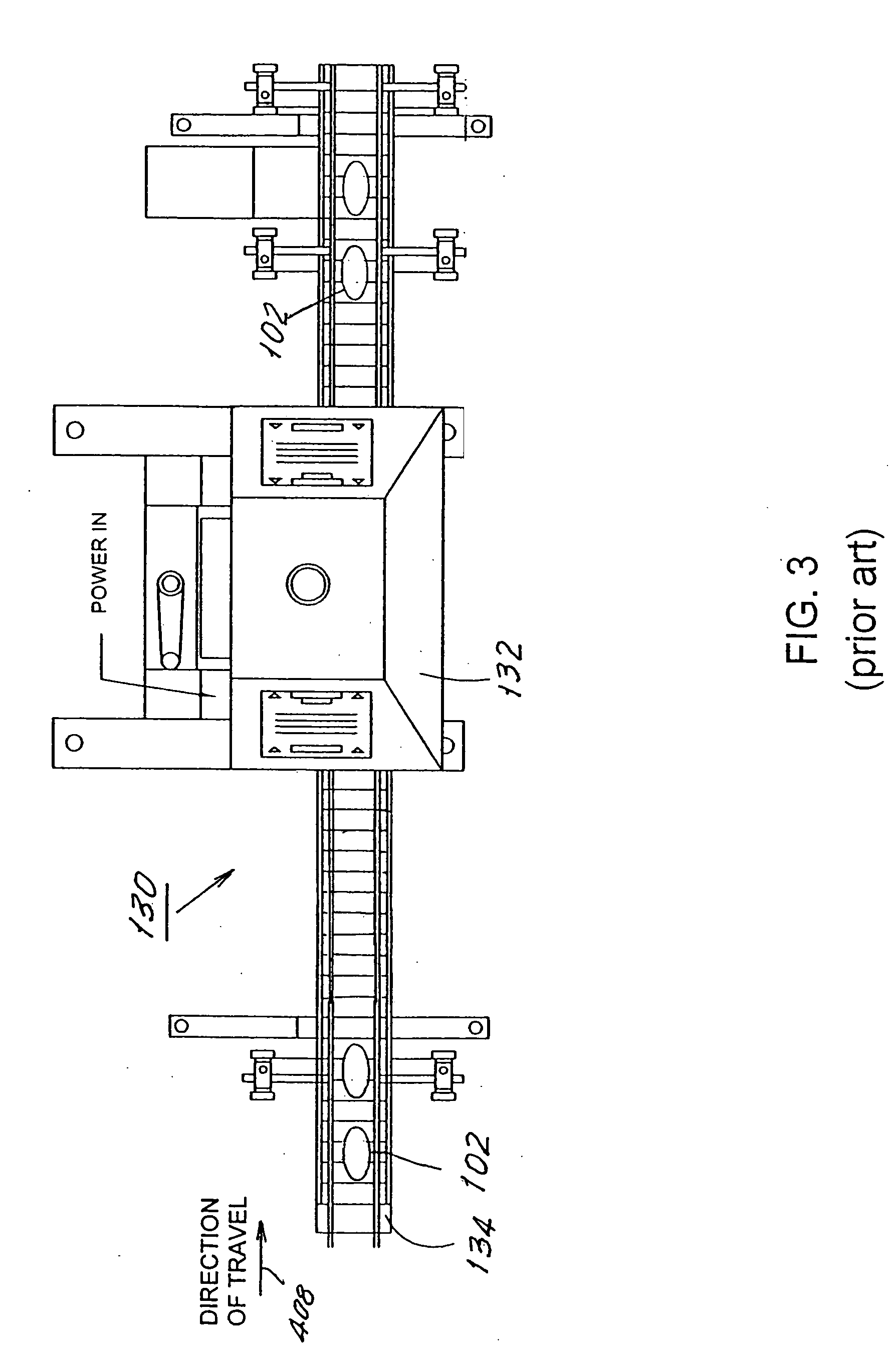
[0041] Referring to FIGS. 4A and 4B, there is illustrated an induction foil cap sealer system 400 according to an embodiment of the present invention with FIG. 4A showing a top plan view of the system and FIG. 4B showing a front plan view. System 400 includes an induction cap sealer unit 402 with an induction head 404. Induction head 404 may resemble any of the example induction heads illustrated in FIGS. 1, 2A, 2B, and 2C, for example. Induction head 404 is preferably positioned over a conveyor belt 406 that transports work pieces (e.g., containers such as bottle 102) under induction head 404. System 400 of the present invention also includes monitoring system 500, a high level functional architecture of which is represented in FIG. 5A. During the sealing operation, work pieces are transported on conveyor belt 406, in direction 408, and under induction head 404 where the work pieces are subjected to induction heating in a conventional manner. Conveyor belt 406 then continues to car...


PUM

PropertyMeasurementUnit
period of timeaaaaaaaaaa
energyaaaaaaaaaa
temperatureaaaaaaaaaa

Abstract

An induction foil cap sealer system includes a monitoring system that comprises a plurality of sensors disposed throughout the sealer system, each sensor monitoring a respective condition related to the sealing operation. A controller is configured to receive from the sensors data representing the monitored conditions and to process this data, determining operating information related to the sealing operation and possibly fault conditions with the sealing operation. The controller is also configured to communicate with a display system and to cause this display system to activate one or more peripheral devices in order to report to a system operator, for example, the determined operating information and/or fault conditions related to the monitored conditions. In reaction to a detected fault condition, the controller may also be configured to shutdown the cap sealer system and/or to remove work pieces that the controller has determined contain a faulty condition.

Description

RELATED APPLICATIONS [0001] This application is based on and claims priority to U.S. Provisional Application No. 60 / 572,027, filed on May 17, 2004, by Kenneth J. Herzog, entitled, “A BAR GRAPH DISPLAY, AN IR THERMOMETER, AND A SPEED SENSOR WHICH CAN BE USED INDIVIDUALLY OR IN COMBINATION WITH AN INDUCTION SEALER,” the contents of which are herein incorporated by reference.BACKGROUND OF THE INVENTION [0002] 1. Field of the Invention [0003] The present invention relates to induction foil cap sealers and more particularly, to an induction foil cap sealer with a monitoring system for monitoring the sealing operation. [0004] 2. Description of the Prior Art [0005] Induction foil cap sealers are well known. Referring to FIG. 1, a prior art induction foil cap sealer includes induction head 100 that includes a plurality of field coils 120. In operation, field coils 120 receive an electrical current that causes the development of magnetic fields that project away from field coils 120. The pro...

Claims


Application Information

Patent Timeline
Patent Type & Authority Applications(United States)
IPC IPC(8): B29C65/00B29C65/02B67B3/26H05B6/02H05B6/06
CPCB29C65/3656B29C66/836B29C66/72321B29C66/90B29C66/949B29C65/3644B29C66/91651B29C66/91221B29C66/91311B29C66/91315B29C66/91411B29C66/91431B29C66/53461B29C66/961B29C66/934B29C66/932B29C66/944B29C65/368B29C66/24221
Inventor HERZOG, KENNETH J.
Owner AUTO KAPS
Why Eureka
Try Eureka