On-board person load sensor

a technology for occupants and sensors, applied in the direction of instruments, force/torque/work measurement apparatus, tractors, etc., can solve the problems of occupant load sensor breakage, seat falling off, complex structure, etc., to accurately measure the load, accurately detect the load, and accurately detect the load

Inactive Publication Date: 2005-12-29
IMASEN ELECTRIC IND
View PDF10 Cites 53 Cited by
  • Summary
  • Abstract
  • Description
  • Claims
  • Application Information

AI Technical Summary

Benefits of technology

[0018] In accordance with a second aspect, the occupant load sensor is fixed to the other of the floor side seat fixing member and the seat side fixing member via the sleeve arranged in the outer periphery of the bolt portion, and the liner member interposed between the sleeve and the through hole in the other of the floor side seat fixing member and the seat side fixing member. Accordingly, a slight motion can be allowed between the bolt portion and the other of the floor side seat fixing member and the seat side fixing member to which the bolt portion is fixed, on the basis of the gap formed between the bolt portion and the sleeve, and the gap between the sleeve and the liner member, and it is possible to cancel the force applied from the other directions than the vertical direction. Therefore, the load from the seat side is applied to the sensor in the vertical direction, and it is possible to accurately detect the load. Further, even if the accuracy of the attaching position of the seat side fixing member with respect to the floor side seat fixing member is low, and the occupant load sensor is attached in a state in which the force in the other directions than the vertical direction is applied, the load from the seat side is applied to the sensor in the vertical direction and it is possible to accurately detect the load because the slight motion is allowed between the bolt portion and the other of the floor side seat fixing member and the seat side fixing member.
[0047] In the ninth aspect to the eleventh aspect, it is preferable that the sleeve is a part of the collar. Since the flange of the collar is brought into contact with the other of the floor side seat fixing member and the seat side fixing member to which the bolt portion is fixed, and the load in the axial (vertical) direction is generated with respect to the sleeve, the load from the seat is applied in the vertical direction, and it is possible to accurately measure the load by the sensor. Further, the number of the parts is small and it is easy to assemble.

Problems solved by technology

In the publications 2 and 3, there is provided a structure in which the occupant load sensor is arranged between the floor side seat fixing member (for example, the rail mount) and the seat side fixing member (for example, the seat rail), and there is a risk that the occupant load sensor is broken at a time of the accident and the seat falls away.
On the other hand, in the publication 1, it is intended to prevent the seat from falling away at a time of the accident by arranging a displacement regulating mechanism in addition to the occupant load sensor, however, there is a problem that the structure becomes complicated and a manufacturing cost is increased due to the independently provided displacement regulating mechanism.
However, in the structure shown in FIG. 15, in the case that an accuracy of an attaching position of the seat rail with respect to the floor side rail mount is low, the occupant load sensor is attached in a state in which the occupant load sensor is inclined, and in a state in which a force in the other directions than a vertical direction is applied, so that there is a problem that a measuring accuracy is lowered.

Method used


Image

  • On-board person load sensor
  • On-board person load sensor
  • On-board person load sensor

Examples


first embodiment

Modified Example of First Embodiment

[0100]FIG. 8 shows an occupant load sensor 10 in accordance with a modified example of the first embodiment, and FIG. 9 shows a state in which the occupant load sensor 10 is attached to the seat rail. FIG. 9B is a side elevational view of the seat rail 40, and FIG. 9A is a cross sectional view along a line A4-A4 in FIG. 9B. FIG. 8A is an explanatory view of an attachment of the occupant load sensor, and FIG. 8B is a cross sectional view along a line B2-B2 in FIG. 9A.

[0101] The occupant load sensor in accordance with the first embodiment is fixed by the bolt 69. On the contrary, the occupant load sensor in accordance with the modified example of the first embodiment is fixed by a shoulder bolt 68 and a bolt 69.

[0102] As shown in FIG. 8B, the occupant load sensor 10 is constituted by a flange portion 20 which is in surface contact with a lower surface of the lower rail (the seat side fixing member) 44 and is attached by the shoulder bolt 68 and th...

second embodiment

Modified Example of Second Embodiment

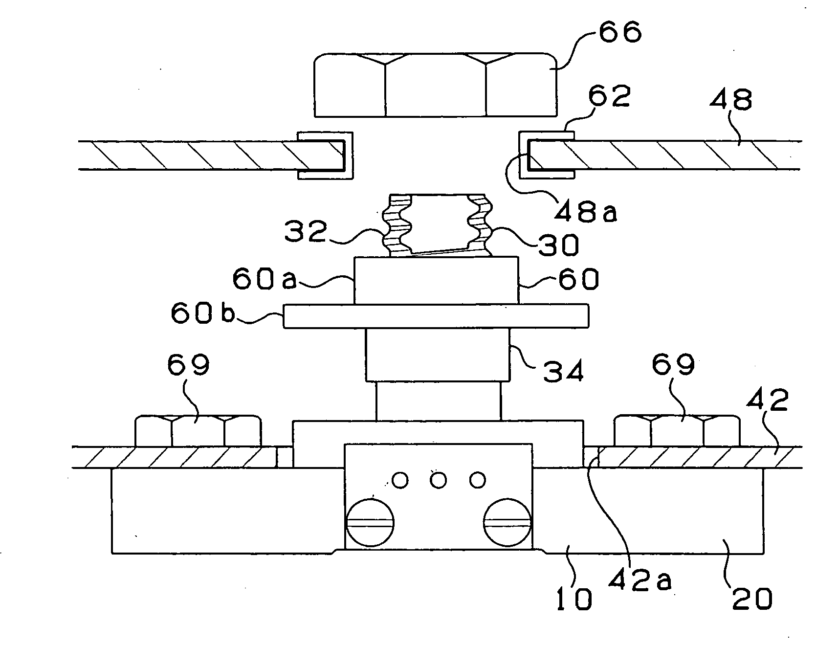
[0112]FIG. 12B is a side elevational view showing a state in which an occupant load sensor in accordance with a modified example of the second embodiment is attached to the seat rail, and FIG. 12A is a cross sectional view along a line A6-A6 in FIG. 12B. The occupant load sensor in accordance with the second embodiment is fixed to the seat rail by the bolt 69. On the contrary, the occupant load sensor in accordance with the modified example of the second embodiment is fixed to the seat rail by the shoulder bolt 68 and the bolt 69. In the modified example of the second embodiment, the occupant load sensor 10 is arranged between the upper rail 42 of the seat rail 40 and the bracket 48 fixing the seat. FIG. 13A is a side elevational view showing a state before the occupant load sensor in accordance with the modified example of the second embodiment is attached to the seat rail, and FIG. 13B is a side elevational view showing a state after being atta...

third embodiment

[0113] A description will be given of an occupant load sensor in accordance with a third embodiment of the present invention with reference to FIG. 14. FIGS. 14A and 14B are explanatory views showing an attached position of the occupant load sensor with respect to the seat in accordance with the first embodiment, and FIG. 14C is an explanatory view showing the occupant load sensor in accordance with the third embodiment.

[0114] In the occupant load sensor 10 in accordance with the first embodiment, as shown in FIG. 14B, in the case that the attached position of a pair of seat rails 40 is largely deflected, the occupant load sensor 10 is attached in a state in which the force in the other directions than the vertical direction is applied, so that it is hard to accurately detect the load. On the contrary, the occupant load sensor 10 in accordance with the third embodiment is structured such that a pair of seat rails 40 are connected via a connection bracket 52, thereby preventing a re...


PUM

PropertyMeasurementUnit
thicknessaaaaaaaaaa
thicknessaaaaaaaaaa
weightaaaaaaaaaa

Abstract

An occupant load sensor (10) is fixed to a bracket (48) via a sleeve (60a) of a collar (60) arranged in an outer periphery of a thread (32) of a bolt portion (30), and a bush (62) interposed between the sleeve (60a) and a through hole (48a) of the bracket (48). Accordingly, a slight movement is allowed between the bolt portion (30) and the bracket (48) on the basis of gaps formed between the thread (32) and the sleeve (60a) and between the sleeve (60a) and the bush (62), and it is possible to cancel a force applied from the other directions than a vertical direction. Therefore, a load from the seat side is applied in the vertical direction and it is possible to accurately detect.

Description

TECHNICAL FIELD [0001] The present invention relates to an occupant load sensor measuring a weight of an occupant seated on a seat of a vehicle. BACKGROUND ART [0002] In order to secure a safety of the occupant, a seat belt and an air bag are provided in a motor vehicle. In recent years, in order to further improve a safety, an operation of the seat belt and the air bag is controlled by identifying an adult or a child, and further in conformity to the weight of the occupant. In particular, in the case that the occupant is an adult, a pretension of the air bag and the seat belt is actuated, and in the case that the occupant is a child, the pretension is not actuated. Alternatively, a developing gas amount and a developing speed of the air bag are adjusted and the pretension of the seat belt is adjusted in conformity to the weight of the occupant. [0003] The identification whether the occupant is an adult or a child mentioned above is generally executed by detecting the weight by an o...

Claims


Application Information

Patent Timeline
Patent Type & Authority Applications(United States)
IPC IPC(8): B60N2/00B60R21/01B60R21/015G01G19/414
CPCB60N2/002B60R21/01516G01G19/4142
Inventor HIDA, TOSHIHIKOOKABE, TAKANORI
Owner IMASEN ELECTRIC IND
Why Eureka
Try Eureka