Multi-way operation switch, input device and input unit

a multi-way operation and switch technology, applied in the direction of mechanical control devices, instruments, manual control with single controlling member, etc., can solve the problems of troublesome operation, and achieve reliable operation, good tactile feedback, and less prone to erroneous operation

Inactive Publication Date: 2005-12-29
PANASONIC CORP
View PDF6 Cites 65 Cited by
  • Summary
  • Abstract
  • Description
  • Claims
  • Application Information

AI Technical Summary

Benefits of technology

[0018] A multi-way operation switch of the present invention includes an operation unit that is horizontally movable and rotatable; a plurality of first switch contacts for turning on and off the electrical coupling by horizontally moving the operation unit; and a second switch contact for turning on and off the electrical coupling by rotating the operation unit. This configuration allows the user to hold a single operation unit and operate multiple electronic apparatuses and setting modes by simply horizontally moving and rotating the operation unit. Accordingly, a smaller multi-way operation switch that is less prone to erroneous operation and which is easier to operate is achievable.

Problems solved by technology

Moreover, the operation is bothersome and erroneous operation is likely to occur, since the button to be pressed needs to be visually checked and operated every time.

Method used


Image

  • Multi-way operation switch, input device and input unit
  • Multi-way operation switch, input device and input unit
  • Multi-way operation switch, input device and input unit

Examples


first exemplary embodiment

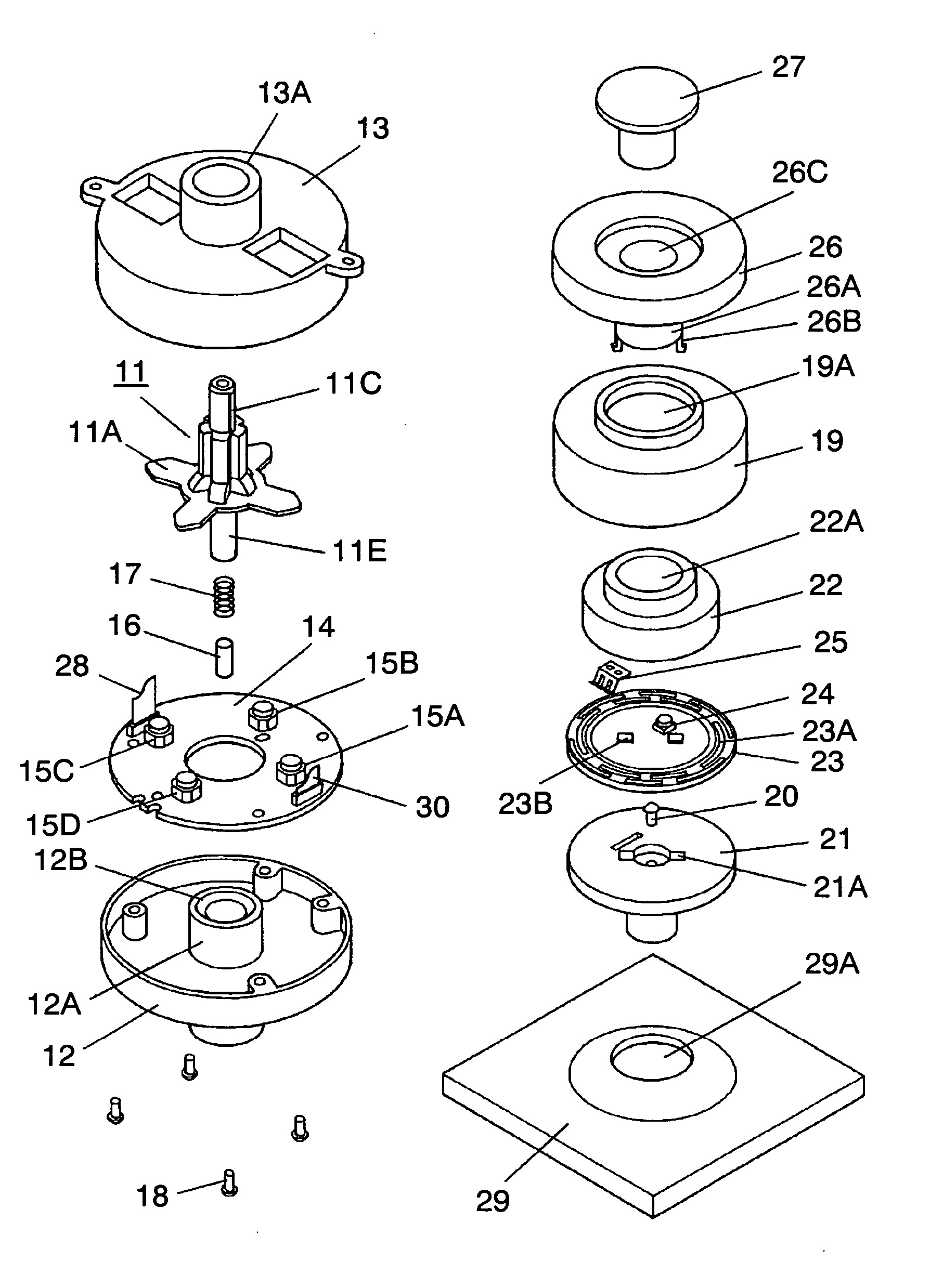
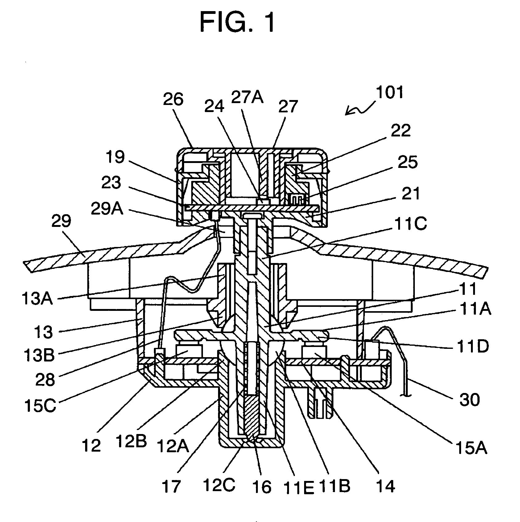
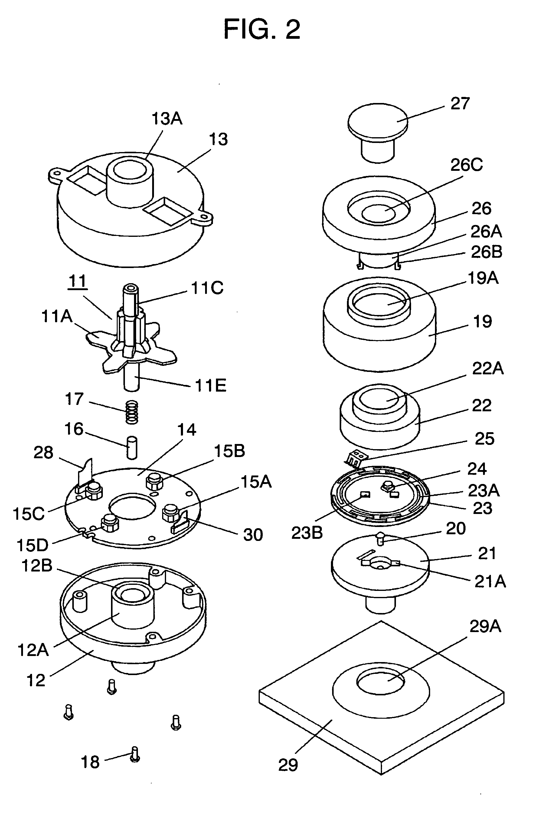
[0034]FIG. 1 is a sectional view and FIG. 2 is an exploded perspective view of multi-way operation switch 101 in accordance with the first exemplary embodiment of the present invention. Multi-way operation switch 101 in the first exemplary embodiment includes working member 11, case 12, cover 13, first printed wiring board 14, push switches 15A to 15D, pin 16, spring 17, screw 18, rotor 19, screw 20, connector 21, driving element 22, second printed wiring board 23, push switch 24, movable piece 25, cap 26, button 27 and connector cable 28. Working member 11, rotor 19, driving element 22, push switch 24, cap 26 and button 27 configure an operation unit of switch 101. The operation unit excluding the working member is called a knob.

[0035] Each component is described next.

[0036] Working member 11 is a roughly cylindrical member made of insulating resin. This working member 11 has arm 11A radially extending in four directions, mutually crossing at the center, and roughly spherical ful...

second exemplary embodiment

[0075] An input device and input unit employing the multi-way operation switch described in the first exemplary embodiment are described in the second exemplary embodiment. The same components are given the same reference numerals in the description.

[0076]FIG. 4 is a block circuit diagram of the input device in this exemplary embodiment of the present invention.

[0077] Input device 50 in the second exemplary embodiment includes operation unit 41, horizontal movement detector 43A, rotation detector 43B, push detector 43C and controller 44. Each component is detailed below.

[0078] Operation unit 41 made of insulating resin includes shaft 41A and roughly cylindrical knob 41B rotatably mounted on the top end of shaft 41A. The bottom end of shaft 41A is retained in box-like case 42 in a rockable manner in each direction of front, back, left and right. Operation unit 41 further has button 41C which can be pushed downward (i.e., vertically) at roughly the center of the top face of knob 41...


PUM


Abstract

A multi-way operation switch of the present invention includes an operation unit that is horizontally movable and rotatable; a plurality of first switch contacts for turning on and off the electrical coupling by horizontally moving the operation unit; and a second switch contact for turning on and off the electrical coupling by rotating the operation unit. This configuration allows the user to hold a single operation unit and operate multiple electronic apparatuses and setting modes by simply horizontally moving and rotating the operation unit. Accordingly, a smaller multi-way operation switch that is less prone to erroneous operation and which is easier to operate is achievable.

Description

BACKGROUND OF THE INVENTION [0001] 1. Field of the Invention [0002] The present invention relates to multi-way operation switches, typically for operating vehicle electronic apparatuses, and input devices and input units employing multi-way operation switches. [0003] 2. Background Art [0004] Increasing numbers of electronic apparatuses such as air conditioner and audio equipment are being installed in vehicles. Input devices with a plurality of switches corresponding to each specific electronic apparatus and setting mode are often installed on the dashboard. Accordingly, there is a need for a user-friendly input device that is less prone to erroneous operation. [0005] A conventional input device of this type is described next with reference to FIG. 7. [0006] As shown in FIG. 7, buttons 2 protrude through openings 1A on panel 1 made of insulating resin. Push switches (not illustrated) which electrically turn on and off by pushing buttons 2 are mounted at the back of buttons 2 on a pr...

Claims


Application Information

Patent Timeline
Patent Type & Authority Applications(United States)
IPC IPC(8): H01H9/00H01H25/04H01H25/06
CPCH01H25/04G05G9/047H01H25/065
Inventor SHITANAKA, HITOKAZUSANTO, KOICHI
Owner PANASONIC CORP
Why Eureka
Try Eureka