Drain valve with flow control

a technology of flow control and drain valve, which is applied in the direction of valve details, valve arrangement, operating means/releasing devices, etc., can solve the problems of high water leakage rate of drain valve, inability to connect to drain valve, and various kinds of property and/or environmental damage, so as to prevent water leakage

Active Publication Date: 2005-12-29
BESTWAY USA A CORP OF DELAWARE
View PDF6 Cites 29 Cited by
  • Summary
  • Abstract
  • Description
  • Claims
  • Application Information

AI Technical Summary

Benefits of technology

[0006] Accordingly, an object of the present invention is to provide a drain valve that prevents leakage of liquids from the container during installation of a drainage hose. A further object of the present invention is to provide a drain valve that is easy to operate under all conditions. Yet another object of the present invention is to provide a drain valve that will withstand repeated use without danger of breakage. Still another object of the present invention is to provide a more robust liquid-container product. SUMMARY
[0008] In one embodiment of the present invention, the restriction cap is comprised of a flow valve that has a flow valve top, flow apertures, a flow valve base, and flow valve threads and a control ring that has a control ring top, a control ring base, a control ring center aperture, and control ring protrusions. The control ring is sealed snugly against the flow valve top by means of an O-ring when the drain valve is in the closed position, in order to prevent liquid leakage through the flow apertures, and is sealed against the side of the flow valve by an O-ring at all times, in order to prevent water leakage via the channel within which the control ring moves in the base ring. The flow valve variably protrudes through the control ring by means of the control ring center aperture. The control ring of the restriction cap twists in and out of the base ring to control the flow of liquid in and out of the drain valve, with the control ring top coming to rest snugly against the top of the base ring when the drain valve is in the fully open position. As the control ring is twisted into the base ring, the control ring protrusions twist into channels inside the base ring and the piston valve is depressed, allowing liquid to flow into the drain valve.
[0009] The drain valve with flow control of the present invention therefore has two modes of operation. By twisting the exterior portion of the control ring, the flow of liquid is either permitted or restricted. Twisting the control ring down into the base ring allows liquid to flow from the container through the flow apertures into the drain valve and then out through the hose connector into the hose. Twisting the control ring out of the base until it meets the flow valve cap causes the control ring base to cover the flow apertures, preventing liquid from flowing from the container into the drain valve.

Problems solved by technology

Further, most of these drain valves are not connectable to hoses for routing the draining liquids to a desired disposal area, instead allowing the liquids to run out directly into the area where the container is located.
This can lead to various kinds of property and / or environmental damage, such as in the case of drainage of chlorinated pool water onto landscaping.
The valve is highly prone to water leakage during attachment of the hose because the prong pushes open the drain plug during installation of the hose connector, before the hose itself has been connected.
The stem connecting the drain plug also presents a weak point that is likely to break with repeated usage, such as would be experienced by an inflatable or portable pool, leading to likely loss of the plug.
Further, there is difficulty with plug removal in any embodiment that does not employ the hose connector prong to push out the drain plug, because of pressure on the plug from the liquid in the container.
Pulling on the plug pull tab to remove the plug under these circumstances exerts extreme stress on the plug pull tab and / or stem, increasing the likelihood of breakage and ultimate loss of the plug.
A further disadvantage is that, if the hose and connector are left connected during use of the pool, the hose and connector will tend to leak water out of the pool because of leakage around the plug.

Method used


Image

  • Drain valve with flow control
  • Drain valve with flow control
  • Drain valve with flow control

Examples


Embodiment Construction

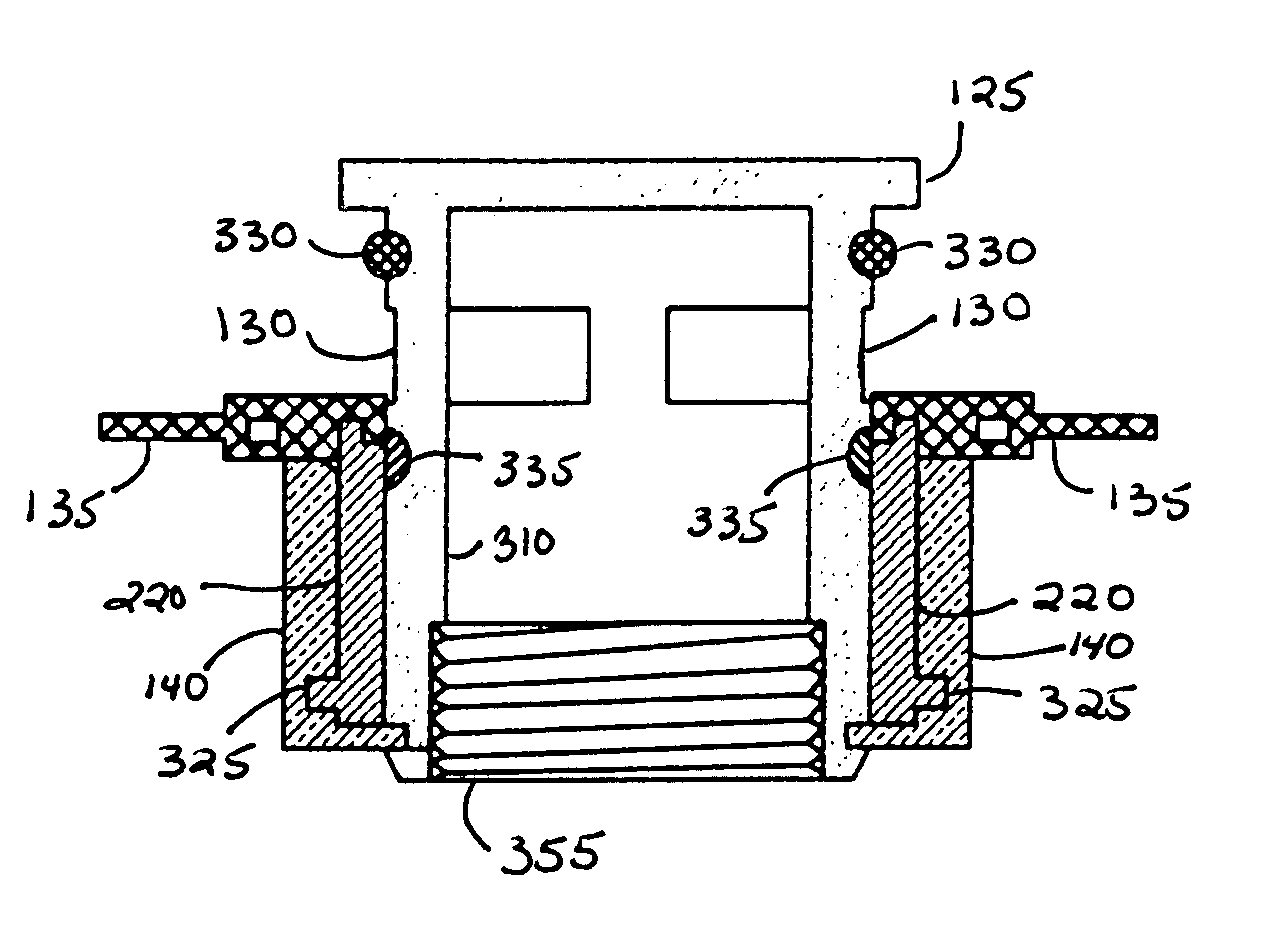
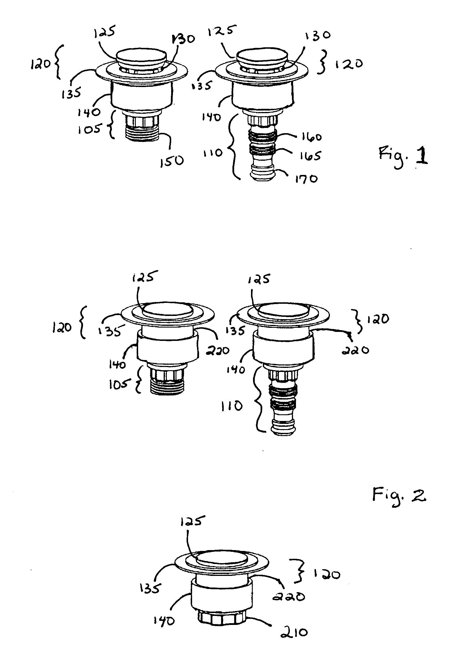
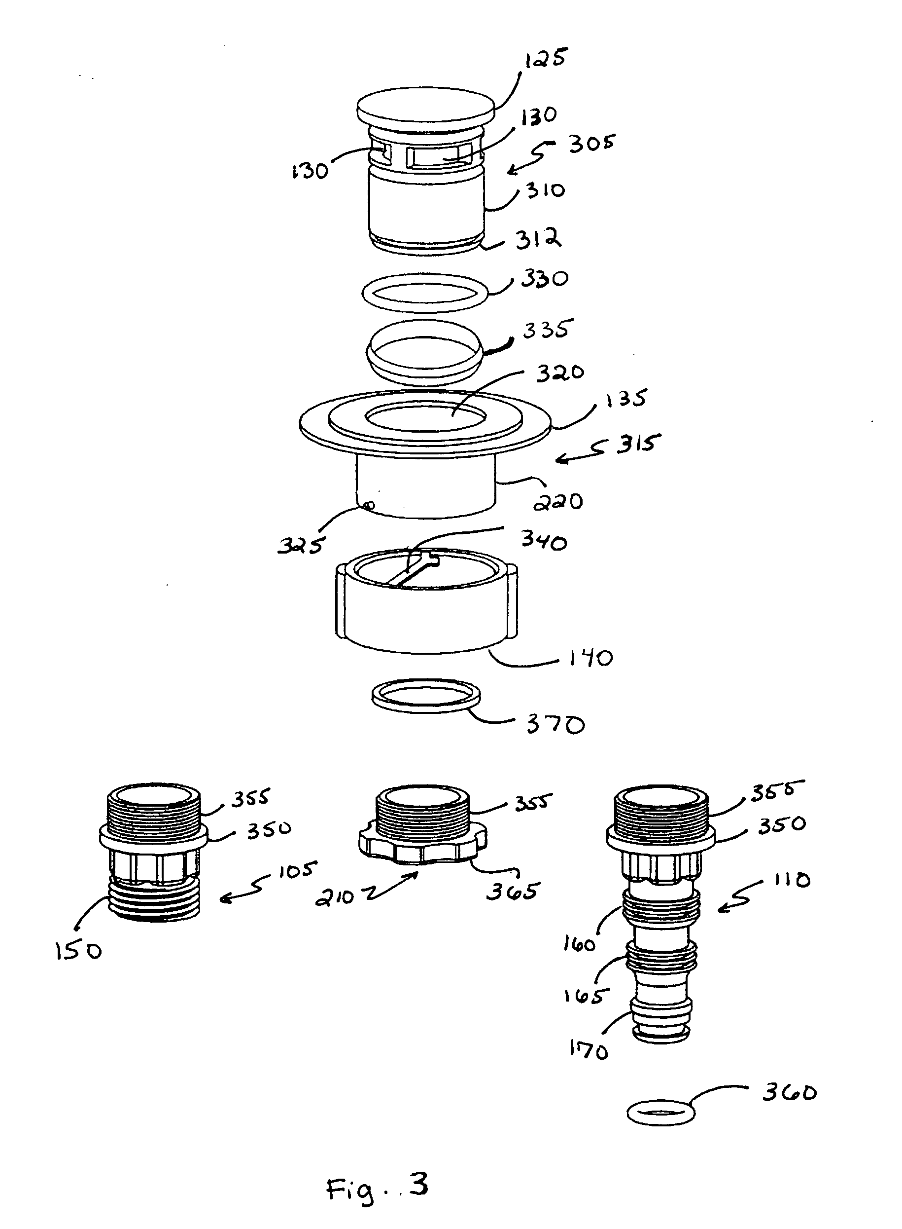
[0016] The present invention is an advanced drain valve with flow control that is designed to control the opening and closing of the drain valve in order to allow liquid to flow into or out of the liquid-container product only when desired. The drain valve of the present invention has a restriction cap that replaces the drain plug found in the prior art drain valves, allowing attachment and detachment of drainage hoses without liquid leakage. It is suitable for use in any style of liquid-container product including, but not limited to, inflatable, portable, and stationary swimming pools, and is much more efficient and user-friendly than the valve of Saputo et al.

[0017] The drain valve with flow control of the present invention has an interchangeable hose connector and a restriction cap having a control ring that twists in and out of a base ring in order to control the flow of liquid in and out of the container. The valve is typically permanently welded into the liquid container at ...


PUM


Abstract

A drain valve with flow control allows liquid to flow into or out of a liquid-container product only when desired by use of a restriction cap having a control ring that twists in and out of a base ring in order to control the flow of liquid in and out of the drain valve. The invention may be used with a wide variety of hose connectors and or safety caps. In one embodiment, the restriction cap is comprised of a flow valve that has a flow valve top, flow apertures, a flow valve base, and flow valve threads and a control ring that has a control ring top, a control ring base, a control ring center aperture, and control ring protrusions. The control ring is sealed snugly against the flow valve top by means of an O-ring when the drain valve is in the closed position, in order to prevent leakage through the flow apertures, and is also sealed against the side of the flow valve by an O-ring, in order to prevent leakage via the channel within which the control ring moves in the base ring. The control ring of the restriction cap twists in and out of the base ring in order to control the flow of liquid in and out of the drain valve. As the control ring is twisted into the base ring, the control ring protrusions twist within channels inside the base ring and the piston valve is depressed, allowing liquid to flow from the drain valve into the hose connector. As the control ring is twisted out of the base ring, the control ring base blocks the flow apertures, preventing liquid from flowing into the drain valve.

Description

FIELD OF THE INVENTION [0001] The invention relates to drain valves for liquid-container products and, in particular, to a drain valve with flow control for use with a large container for liquids. BACKGROUND [0002] Today's large liquid-container products, such as both portable and stationary above-ground swimming pools containing water, typically have a drain valve to allow removal of the liquid, either for storage of the portable container or during the winter season for the stationary one. Most of these drain valves require that the user insert his or her hand into the water in order to plug or unplug the drain valve. Further, most of these drain valves are not connectable to hoses for routing the draining liquids to a desired disposal area, instead allowing the liquids to run out directly into the area where the container is located. This can lead to various kinds of property and / or environmental damage, such as in the case of drainage of chlorinated pool water onto landscaping. ...

Claims


Application Information

Patent Timeline
Patent Type & Authority Applications(United States)
IPC IPC(8): F16K3/26F16K31/44F16K31/528
CPCF16K3/265F16K31/5286F16K31/445
Inventor HUANG, CHAOYANG
Owner BESTWAY USA A CORP OF DELAWARE
Why Eureka
Try Eureka