Rechargeable battery module

Inactive Publication Date: 2005-12-29
SAMSUNG SDI CO LTD
View PDF3 Cites 40 Cited by
  • Summary
  • Abstract
  • Description
  • Claims
  • Application Information

AI Technical Summary

Benefits of technology

[0014] The present invention provides a rechargeable battery module that has superior te

Problems solved by technology

The addition of these components results in an increase in the volume of the battery module.
This technique has the drawback of making it difficult to dissipate heat that is generated in the respective unit batteries.
For an HEV comprising the battery module, the de

Method used


Image

  • Rechargeable battery module
  • Rechargeable battery module
  • Rechargeable battery module

Examples


Example

[0024] The battery module of the present invention may effectively be used in an apparatus that uses a motor such as a hybrid electric vehicle (HEV), an electric vehicle (EV), a wireless device, an electric-powered bicycle, an electric-powered scooter, and the like.

[0025] According to the present invention, the arrangement of the unit batteries in the battery module may be improved and thus the volume of the battery module may be minimized. Further, the connection between the unit batteries in the battery module and the structure for the gas emission may be shared, thus simplifying the structure of the battery module.

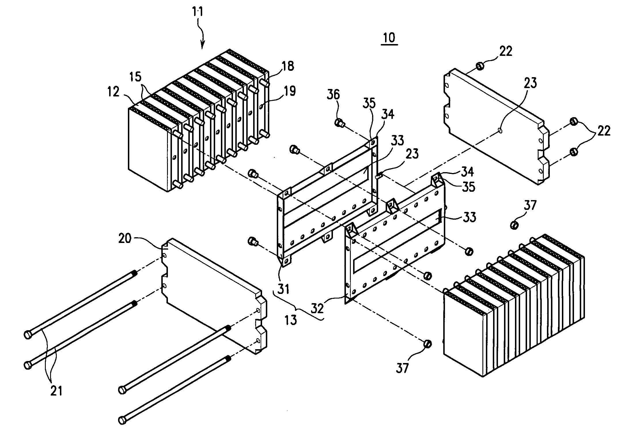
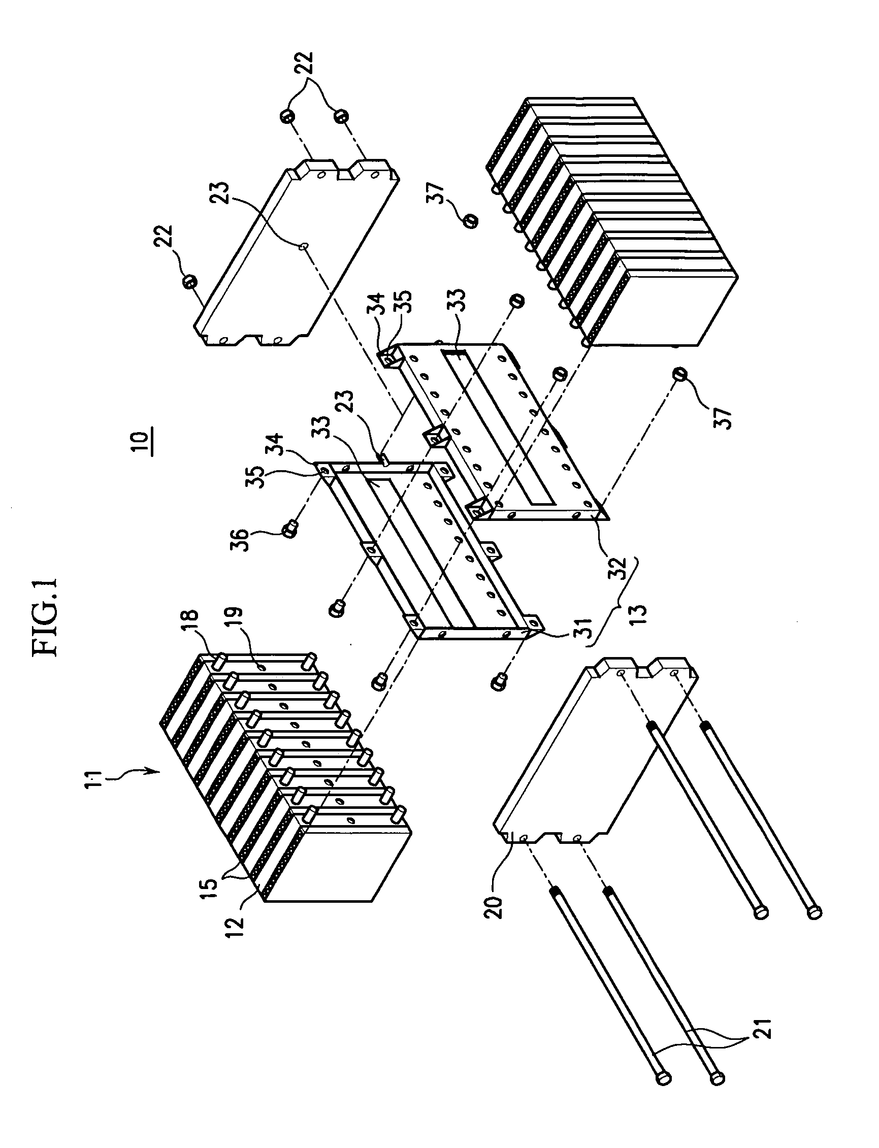
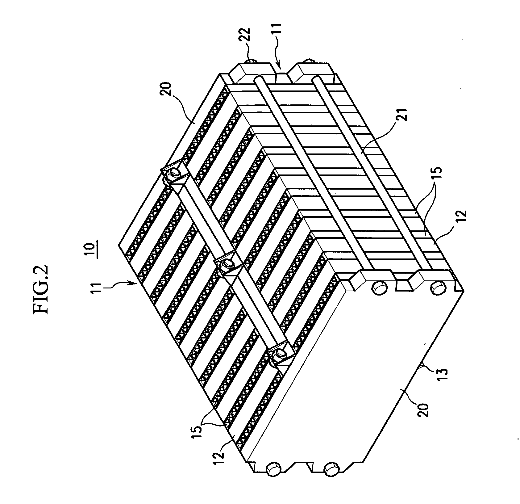
[0026]FIG. 1 is an exploded perspective view that schematically shows a configuration of a rechargeable battery module according to an exemplary embodiment of the invention. FIG. 2 is a perspective view that schematically shows a state in which the rechargeable battery module according to the exemplary embodiment of the invention is assembled. FIG. 3 is a top sectiona...


PUM


Abstract

A rechargeable battery module that exhibits superior temperature control and has a minimized size through an efficient arrangement of unit batteries is provided. The rechargeable battery module has a plurality of unit batteries that are arranged at constant intervals and a housing that holds the unit batteries and in which air for controlling a temperature of each of the unit batteries flows. The unit batteries are divided into two battery columns that are provided on either side of a central structure such that terminals of the unit batteries in different columns face each other.

Description

CROSS REFERENCE TO RELATED APPLICATION [0001] This application claims priority to and the benefit of Korean Patent Application No. 10-2004-0048156, filed on Jun. 25, 2004, which is hereby incorporated by reference. BACKGROUND OF THE INVENTION [0002] (a) Field of the Invention [0003] The present invention relates to a rechargeable battery. In particular, the present invention relates to a rechargeable battery module that has an improved arrangement of unit batteries that minimizes the overall volume of the rechargeable battery module when the unit batteries are connected to form the rechargeable battery module. [0004] (b) Description of the Related Art [0005] In recent years, high-power rechargeable batteries that use non-aqueous electrolytes that have high energy densities have been developed. For example, a plurality of high-power rechargeable batteries may be connected together in series to form a large-scale rechargeable battery that can drive a motor in a high-power apparatus su...

Claims


Application Information

Patent Timeline
IPC IPC(8): H01M10/00H01M10/02H01M50/209H01M50/264H01M50/289H01M50/529H02J7/00
CPCH01M2/1077H01M2/12H01M2/206H01M10/5073H01M10/5004H01M10/5032H01M10/5059H01M10/0481H01M10/647H01M10/6557H01M10/6566H01M10/613Y02E60/10H01M50/30H01M50/209H01M50/289H01M50/264H01M50/20H01M50/529
Inventor KIM, TAE-YONG
Owner SAMSUNG SDI CO LTD
Why Eureka
Try Eureka