AC magnetic tracking system with non-coherency between sources and sensors

a tracking system and non-coherent technology, applied in the direction of electrical/magnetic measuring arrangements, instruments, point-to-point measurements, etc., can solve the problems of error signals caused by magnetic signals, causing responses that distort data, and always difficult to achiev

Inactive Publication Date: 2005-12-29
ALKEN INC DBA POLHEMUS
View PDF15 Cites 13 Cited by
  • Summary
  • Abstract
  • Description
  • Claims
  • Application Information

AI Technical Summary

Problems solved by technology

This approach (see FIG. 2) always has proved difficult since the magnetic near field drops off as the third order of range from the source.
Another factor is the error signal caused by magnetic signals creating responses that distort data because of eddy currents induced in nearby conductive materials.
Consequently, increasing source drive in order to increase operating range creates no benefit over most of the volume because distortion continues as a serious problem.
Hence, a large magnetic field source is quite limited in extending operating range.
If the source drive level is kept low such that the effects of secondary fields from eddy currents tends to fall at or below the noise floor of the sensing circuitry, that is the source-sensor coupling range is kept short, distortion is rarely a significant problem.
Of course, operation of several static sensors in order to track a source pseudo-“sensor” raises the issue of maintaining several movement reference points in the volume.
Fortunately, referencing movement back to a common point is a relatively simply geometry problem with somewhat more complex bookkeeping of the various known sensor data points and the computation of track data.
What makes this tracking over a larger area difficult is the incoherency of signal frequencies between a remote wireless source and the tracking sensor(s).
However, existing systems do not provide the freedom to move through a 3D volume with or without being wired.
However, the systems cited remained tethered through cabling and greatly simplified the engineering problem of signal detection, synchronization and tracking.
These constraints, plus a requirement to perform calibrations at over 32 position and 32 orientation settings, leads to significant complexity, considering that phase adjustments are subject to drift over time.

Method used


Image

  • AC magnetic tracking system with non-coherency between sources and sensors
  • AC magnetic tracking system with non-coherency between sources and sensors
  • AC magnetic tracking system with non-coherency between sources and sensors

Examples


Embodiment Construction

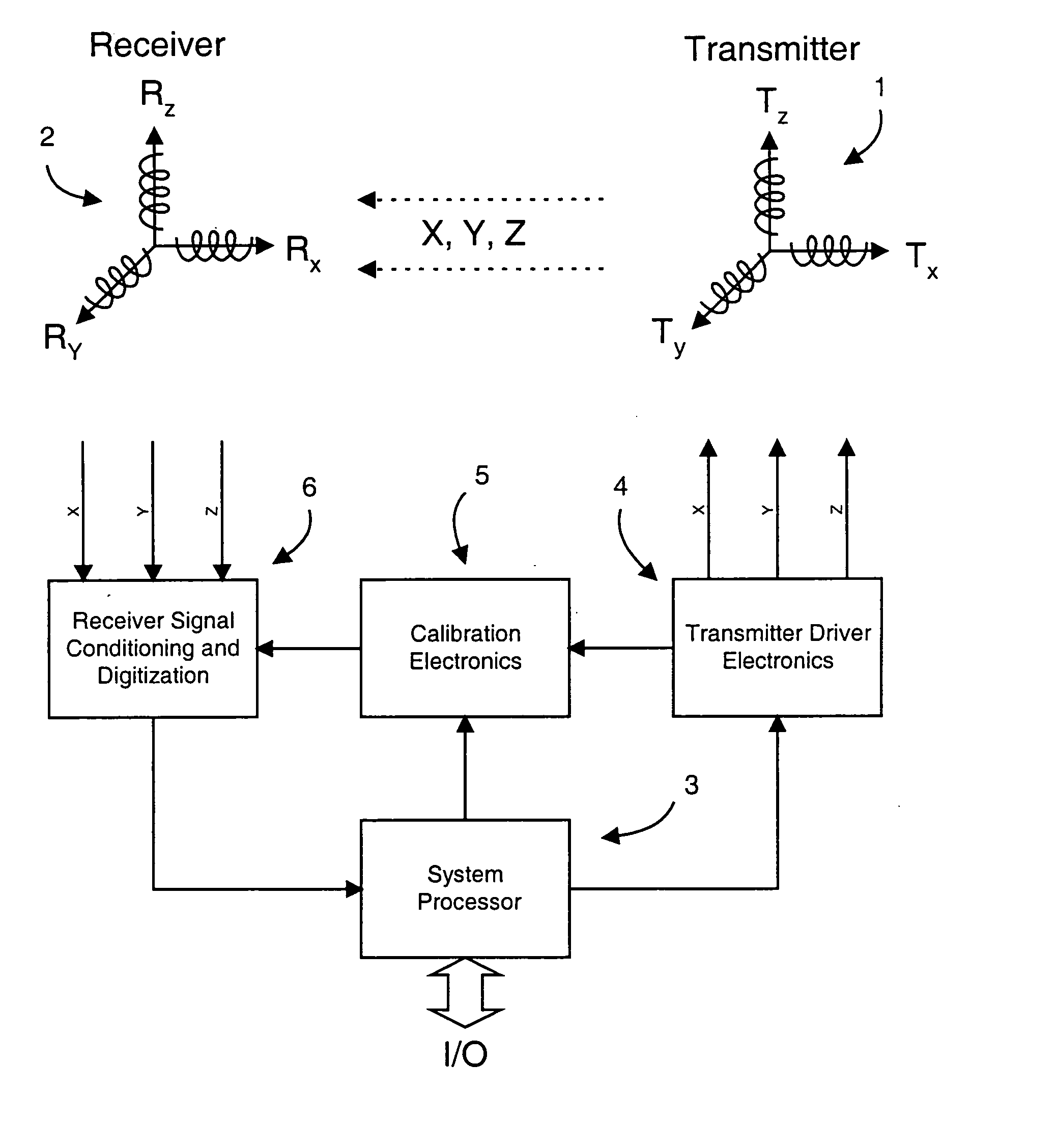
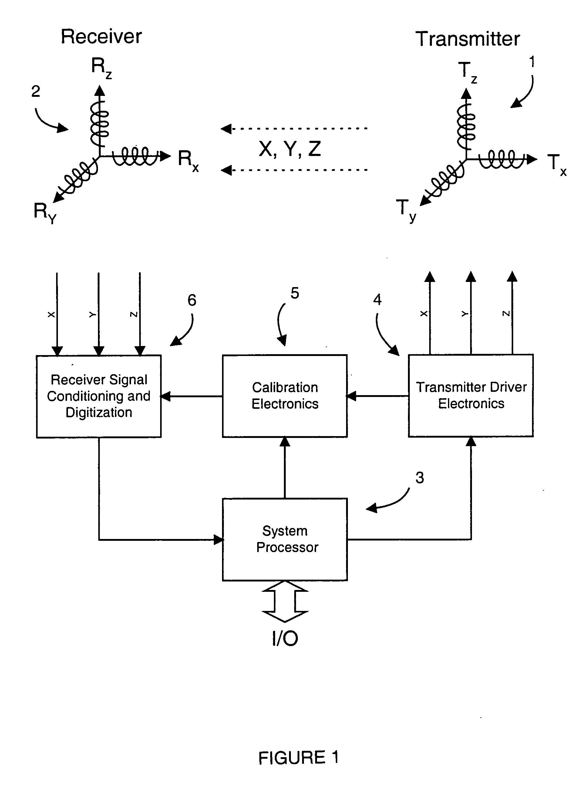
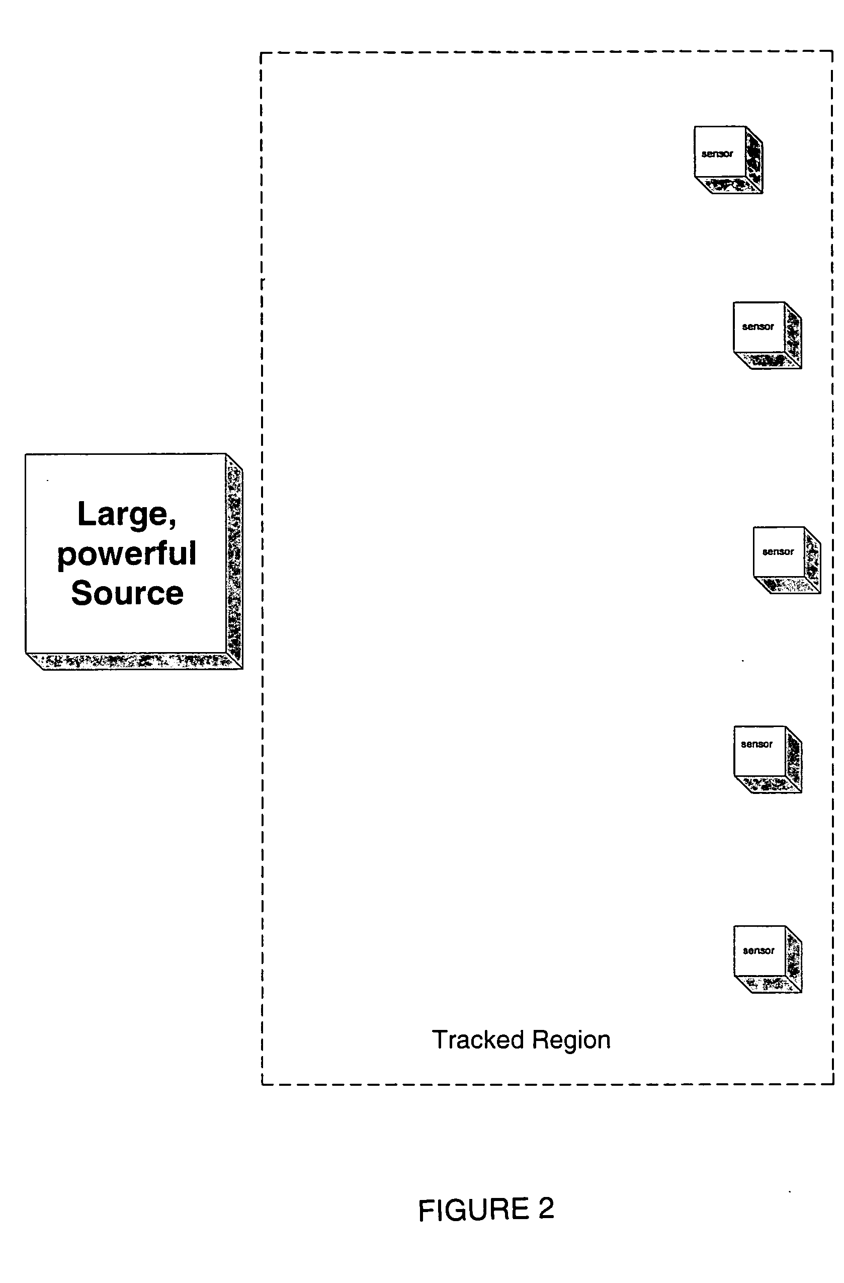
[0020] If one desires a remote “sensor” to track, it really does not matter whether the source or sensor is tracked because the P&O calculation is the relative position and orientation between source and sensor. If adequate sensitivity and low noise performance can be achieved with the sensor and a means can be found to determine the source frequency / frequency set and become synchronized with this external source of orthogonal fields, then the source can be remotely disposed as a “pseudo-sensor.” Furthermore, once this is accomplished and there is no constraint placed on the source signals except that they create signals from a frequency population consistent with the system, there can be sources both wireless and wired being tracked as pseudo-sensors. Applicable wireless configurations are disclosed in co-pending U.S. Provisional Patent Application Ser. No. 60 / 578,128, the entire content of which is incorporated herein by reference.

[0021] The reciprocity of the tracking relationsh...


PUM


Abstract

In an AC magnetic tracker one or more multi-axis field sources, each operating at a different frequency, or frequency set, are detected and tracked in three-dimensional space, even when wireless or otherwise not physically connected to the tracking system. Multiple sources can be tracked simultaneously as they each operate with their own unique detectable set of parameters. The invention not only provides the ability to uniquely identify one or more sources by their frequencies, but also to synchronize with these frequencies in order to measure signals that then allow tracking the position and orientation (P&O) of the source(s). Further, these sources need not be present at the time of system start-up but can come and go while being detected, discriminated and tracked. It also should be noted that application of such systems in multiples with more sensors not synchronized to a source or sources also could be employed to give the reverse appearance of a known source phase and incoherency with the sensors.

Description

REFERENCE TO RELATED APPLICATION [0001] This application claims priority to U.S. Provisional Patent Application Ser. No. 60 / 577,860, filed Jun. 8, 2004, the entire content of which is incorporated herein by reference.FIELD OF THE INVENTION [0002] This invention relates generally to AC magnetic tracking systems and, in particular, to detecting and establishing phase coherency between magnetic signal sources and sensors. BACKGROUND OF THE INVENTION [0003] Position and orientation tracking systems (“trackers”) are well known in the art. For example, U.S. Pat. Nos. 4,287,809 and 4,394,831 to Egli et al.; U.S. Pat. No. 4,737,794 to Jones; U.S. Pat. No. 4,314,251 to Raab; and U.S. Pat. No. 5,453,686 to Anderson, are directed to AC electromagnetic trackers. U.S. Pat. No. 5,645,077 to Foxlin discloses an inertial system, and combination systems consisting of two different trackers, such as optical and magnetic, are described in U.S. Pat. No. 5,831,260 to Hansen and U.S. Pat. No. 6,288,785 B...

Claims


Application Information

Patent Timeline
Patent Type & Authority Applications(United States)
IPC IPC(8): G01B7/004G01J1/20
CPCG01B7/004
Inventor HIGGINS, ROBERT F.JONES, HERBERT R. JR.RODGERS, ALLAN G.
Owner ALKEN INC DBA POLHEMUS
Why Eureka
Try Eureka