AC magnetic tracking with phase disambiguation

a technology of phase disambiguation and magnetic tracking, applied in the field of magnetic locators, can solve the problems of undesirable or impractical direct connection between the sender and the sensor, receiver cannot detect the phase of the signal used to drive the transmitter coil without ambiguity

Active Publication Date: 2009-03-19
ALKEN INC DBA POLHEMUS
View PDF10 Cites 15 Cited by
  • Summary
  • Abstract
  • Description
  • Claims
  • Application Information

AI Technical Summary

Benefits of technology

[0014]A further aspect of the invention provides magnetic locating systems. The magnetic locating system in accordance with this aspect of the invention includes a transmitter having a plurality of co-located orthogonal transmit coils and a transmitter circuit arranged to actuate the coils in the manner discussed above. For example, the transmitter circuit may include a drive circuit associated with each of the transmit coils, a carrier frequency generator for generating a carrier frequency signal and a multiplexer for applying the carrier frequency signal to the various drive circuits in succession. By using the same carrier frequency signal to actuate all of the drive circuits and hence all of the coils, the system assures coherence between the alternating magnetic fields emitted by the various coils.

Problems solved by technology

In some applications, however, a wire or other direct connection between the sender and the sensor is undesirable or impractical.
In general, the receiver cannot detect the phase of the signals used to drive the transmitter coils without ambiguity.

Method used


Image

  • AC magnetic tracking with phase disambiguation
  • AC magnetic tracking with phase disambiguation
  • AC magnetic tracking with phase disambiguation

Examples


Embodiment Construction

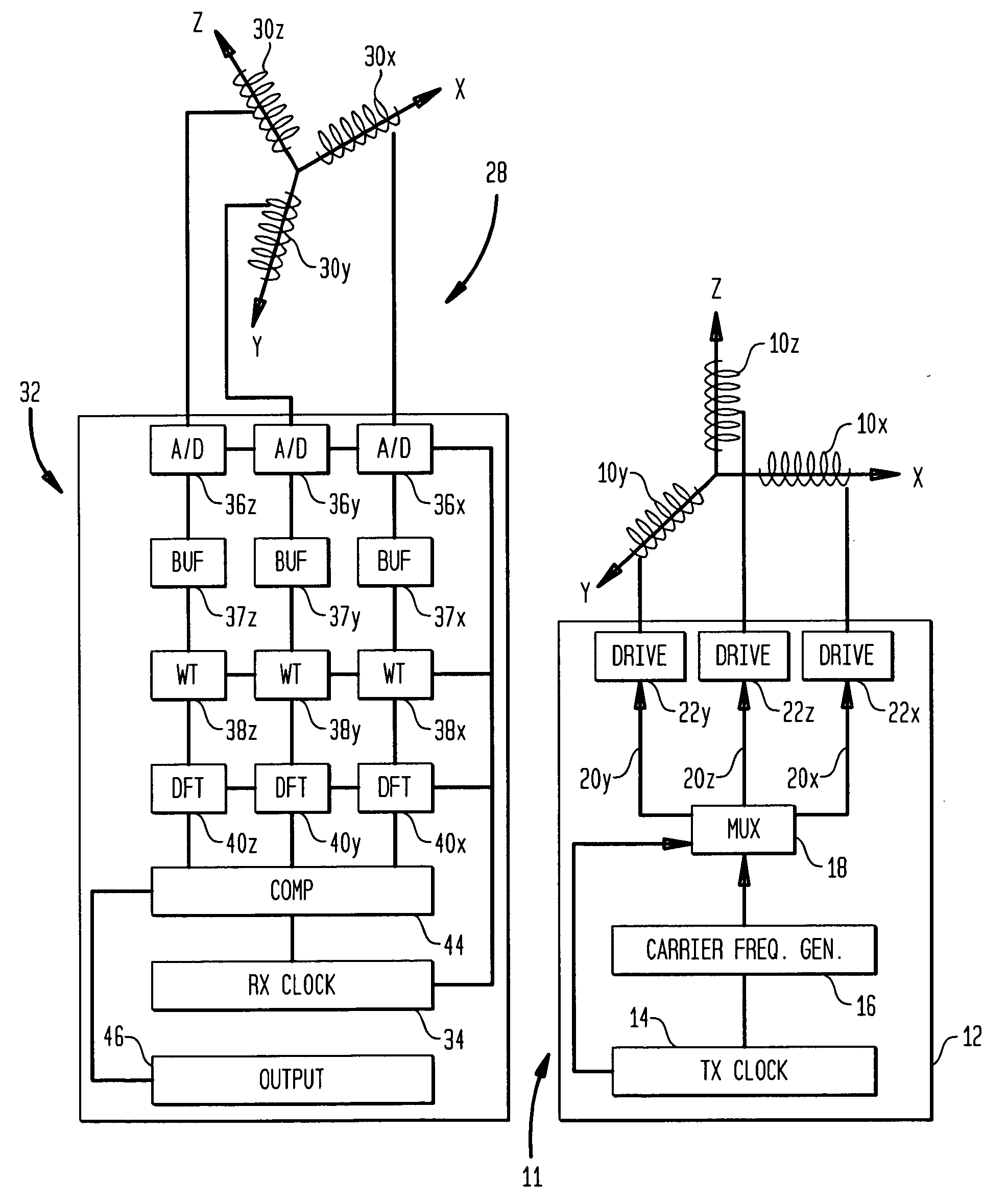
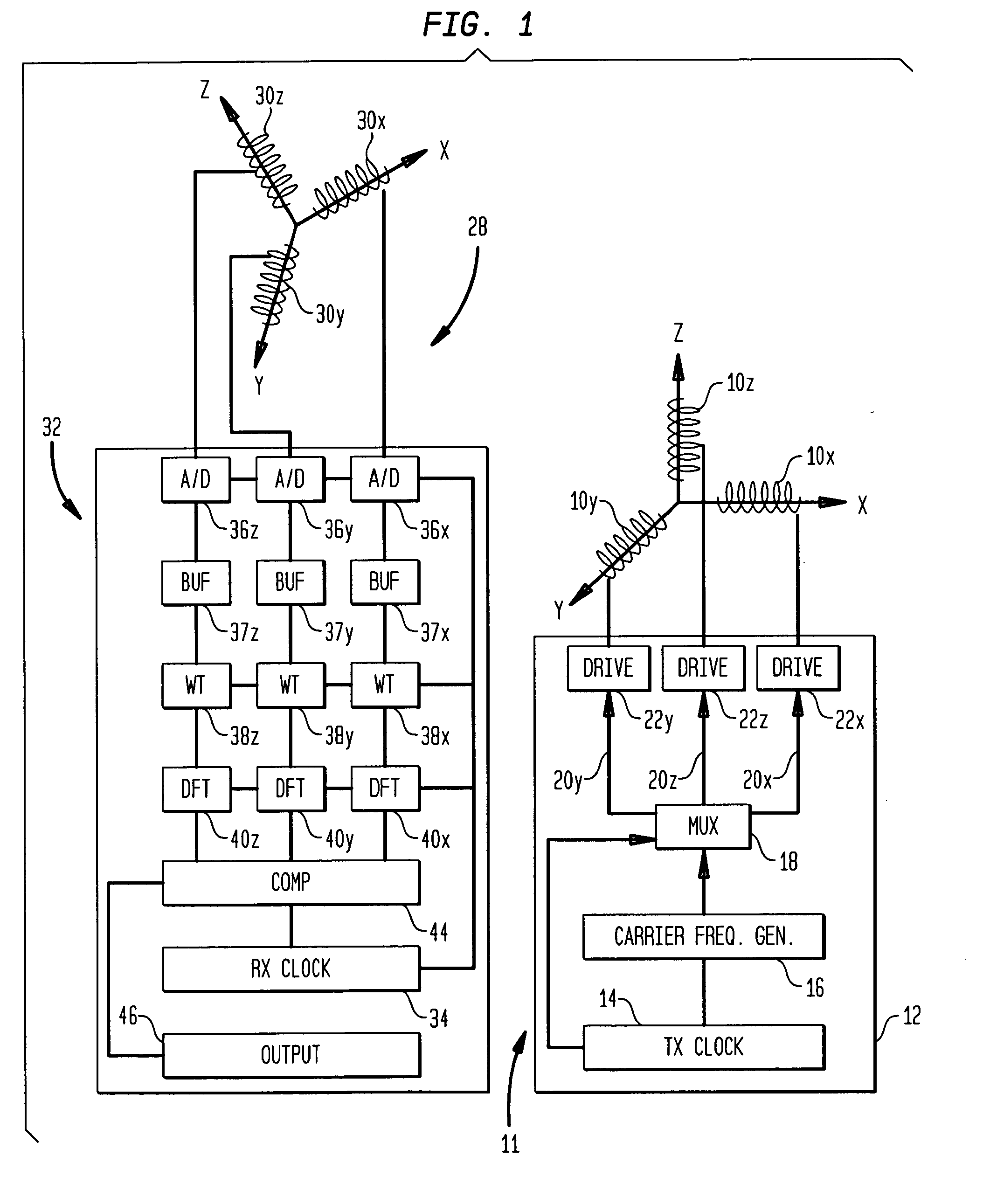
[0020]In the description below and the accompanying drawings, functional elements of the receiver are shown and described as separate circuits for ease of understanding. Likewise, functional elements of the transmitter are shown and described as separate circuits. However, this should not be taken as requiring separate physical components. For example, a programmable component such as a microprocessor or ASIC may be arranged to fulfill the roles of different circuit elements at different times, and a single component may serve as part or all of two or more of the functionally-described separate circuits. Merely by way of example, many or all of the functions of the receiver control circuit 32 (FIG. 1) may be performed by a programmable signal processing chip.

[0021]A transmitter 11 in accordance with one embodiment of the invention includes a set of three collocated coils 10x, 10y and 10z disposed along three mutually orthogonal axes, arbitrarily labeled “X,”“Y,” and “Z”. The axes of...


PUM


Abstract

A method and system for magnetic locating resolves phase ambiguity. The system uses time-division multiplexed magnetic fields emitted from plural transmit coils. The magnetic fields are alternating fields at a carrier frequency, and the fields emitted from different coils in different transmit intervals have known phase relationship with one another as, for example where the alternating fields are coherent with one another. A receiver uses a plurality of sensor coils and derives plural components using the common phase reference or plural phase reference times having a known relationship. If the determinant of a matrix of the components has a first value, the phase information in the components is correct, and position and orientation are derived from the components. If the determinant has a second value, the phase information in the components is incorrect. In this case, corrected components are formed by shifting the phases of the components π radians; the position and orientation are derived from the corrected components.

Description

CROSS-REFERENCE TO RELATED APPLICATIONS[0001]The present application claims benefit of the filing date of U.S. Provisional Patent Application No. 60 / 993,875, filed Sep. 14, 2007, the disclosure of which is incorporated by reference herein.FIELD OF THE INVENTION[0002]The present invention relates to magnetic locators, commonly also referred to as magnetic tracking systems.BACKGROUND OF THE INVENTION[0003]A magnetic tracking system includes a sender or transmitter which applies magnetic fields in space, and a sensor which detects the fields. Most commonly, the transmitter includes three coils directed along three mutually orthogonal axes. Typically, these coils are co-located, i.e., wound so that their centers are at or very near to the same point in space. The sensor or receiver typically includes a similar assembly of three coils or other sensors. The position and orientation of the receiver in the frame of reference of the transmitter can be determined from the set of relationships...

Claims


Application Information

Patent Timeline
Patent Type & Authority Applications(United States)
IPC IPC(8): G01B7/00G01R33/02
CPCA61B5/06A61B5/7257A61B5/1077A61B5/062
Inventor HIGGINS, ROBERT F.
Owner ALKEN INC DBA POLHEMUS
Why Eureka
Try Eureka