
Self-training AC magnetic tracking systems to cover large areas

a tracking system and self-training technology, applied in the field of ac magnetic tracking systems, can solve the problems of increasing the source drive in order to increase the operating range without any benefit, causing error signals, and avoiding most field distortion, so as to reduce field distortion and shorten the separation of the source and the sensor

Inactive Publication Date: 2006-02-23
ALKEN INC DBA POLHEMUS
View PDF17 Cites 14 Cited by
  • Summary
  • Abstract
  • Description
  • Claims
  • Application Information

AI Technical Summary

Benefits of technology

[0015] This invention broadly resides in self-calibrating the AC magnetic tracking system, and combination “outside-in” and “inside-out” architectures offering unique motion tracking capabilities. A goal of the invention is to cover more area with minimal distortion, and use the tracking system itself to determine overall P&O based on the P&O of an initial, reference marker (or magnetic field sources or sensors). In this way the tracking system can report the output as anticipated and needed by the user without confusion and without costly and time-consuming metrology while covering a large region when distance from the reference may be great.
[0016] Apparatus and methods are described. A method according to the invention includes the steps of positioning a plurality of stationary AC magnetic “markers” in a tracking volume and moving a mobile AC magnetic marker counterpart (i.e., sensor for sources; source for sensors) proximate to a first one of the stationary markers designated as a reference marker. The position and orientation (P&O) of the mobile marker is determined relative to the reference marker, then moved so as to be proximate to a second one of the stationary markers. The P&O of the second marker is determined relative to the reference marker, allowing the P&O of the mobile marker to be determined relative to the reference marker based upon the P&O of the second marker relative to the reference marker.
[0019] According to the “sensor learn” embodiment of the invention, at least one 3-axis field source, operating at a set of frequencies for the three orthogonal axes, is detected at one reference three-axis sensor. The result is then used to locate subsequent monitoring sensors in the three-dimensional measurement space. The sources can be operated under pre-determined rules, which allow an environment to be lined with monitoring sensors that can be used to report back to the outside world measurements relative to the reference sensor. In this way, the system itself can be used to align its measurement space for meaningful results to the measurement sensor although the range from reference sensor to a later position of the source can be far out of range from normal coupling of signals between them but still be properly referenced geometrically.
[0020] In the “source learn” configuration, at least one 3-axis reference field source, operating at a set of frequencies for the three orthogonal axes is placed in a fixed location, detected with a three-axis sensor, and its P&O is computed. Then the P&O determined from subsequent sources distributed in the environment can be translated and rotated to the location coordinates of this reference source. Subsequent fixed sources operating at a different frequency set can be located in the same way and have their P&O measurements translated and rotated to the location of the reference source. These sources operated under these simple rules allow an environment to be traversed with sensors whose P&O measurements always can be reported back to the outside world relative to the reference source. In this way, the system itself can be used to align its measurement space for meaningful tracking results over extended ranges far outside normal coupling of signals between individual source and sensor sets but still be properly referenced geometrically while avoiding most field distortion because of the small fields and short source-sensor separations.
[0021] Thus, depending upon the configuration, the tracking system learns the source placement configuration and then reports subsequent results referenced to a particular small field source location. In an alternative embodiment, signal source markers are tracked by fixing sensors in place, and then the tracking system learns their locations based upon the location of a single sensor. In a robust implementation supporting both “inside-out” and “outside-in” operation, the sensor / source learn concepts are combined to yield still more novel options for 3D tracking system configurations. Distributed sources operating at different, distinguishable frequency sets and sensors monitoring mobile “marker” sources also operating at different frequency sets provide unique motion tracking architectures. Further, these system configurations also exhibit the characteristic of reduced field distortion through short source-sensor separations.

Problems solved by technology

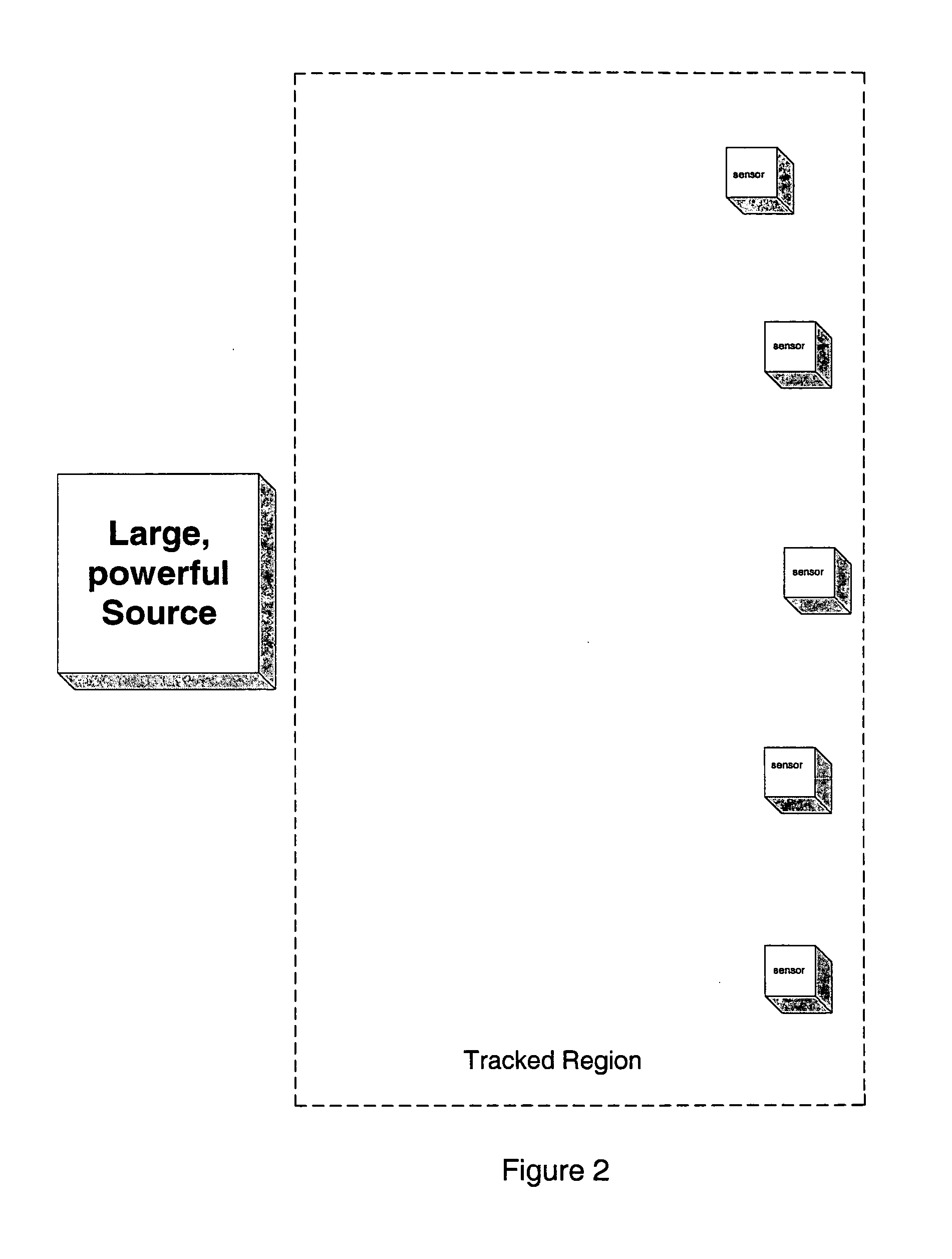
This approach (FIG. 2) has proved difficult, however, since the magnetic near-field drops off as the third order of range from the source.
Another factor to be considered is the error signal caused by magnetic signals creating responses that distort data due to eddy currents induced in nearby conductive materials.
Consequently, increasing source drive in order to increase operating range creates no benefit over most of the volume because distortion continues as a serious problem.
Hence, a large magnetic field source is quite limited in extending useful operating range in distortion-prone environments.
If the source drive level is kept low such that the effects of secondary fields from eddy currents tends to fall at or below the noise floor of the sensing circuitry, distortion is rarely a significant problem.
Gilboa, however, does not address the issue of defining the region in which his wireless sensor navigates, apparently counting on a single sensor reporting the P&O relative to the source.
Nor do we know of a system whereby time multiplexing between two field sources is used to gain coverage over a larger area, but such an approach halves the tracking update rate.

Method used


Image

  • Self-training AC magnetic tracking systems to cover large areas
  • Self-training AC magnetic tracking systems to cover large areas
  • Self-training AC magnetic tracking systems to cover large areas

Examples


Embodiment Construction

[0054] An important aspect of this invention is to use the tracking system itself to determine P&O in a sequence along any continuous path of a moving “marker” based on the P&O of a beginning, reference position. In this way, the tracking system can report the output as anticipated and needed by the user without confusion and without costly and time-consuming metrology. The approach is applicable to sensor and source learning in conjunction with both outside-in and inside-out structures. By virtue of the invention, the system itself assumes the responsibility of reporting out all tracking data relative to a single reference point.

[0055] In a first example described herein below, we teach the use of a tracking system to learn the source placement configuration and then report subsequent results to the outside world referenced to a particular small field source location. According to a second disclosed example, we teach how signal source markers can be tracked by fixing sensors in pl...


PUM


Abstract

Self-calibrating AC magnetic tracking systems and combination “outside-in” and “inside-out” architectures offer unique motion tracking capabilities. More area is covered with minimal distortion using the tracking system itself to determine overall P&O based on the P&O of an initial, reference marker. The output as anticipated and needed by the user is output without confusion and without costly and time-consuming metrology while covering a large region when distance from the reference may be great. A method according to the invention includes the steps of positioning a plurality of stationary AC magnetic “markers” in a tracking volume and moving a mobile AC magnetic marker proximate to a first one of the stationary markers designated as a reference marker. The position and orientation (P&O) of the mobile marker is determined relative to the reference marker, then moved so as to be proximate to a second one of the stationary markers. The P&O of the second marker is determined relative to the reference marker, allowing the P&O of the mobile marker to be determined relative to the reference marker based upon the P&O of the second marker relative to the reference marker. The stationary markers may be AC magnetic sensors, with the mobile marker being an AC source, or vice-versa.

Description

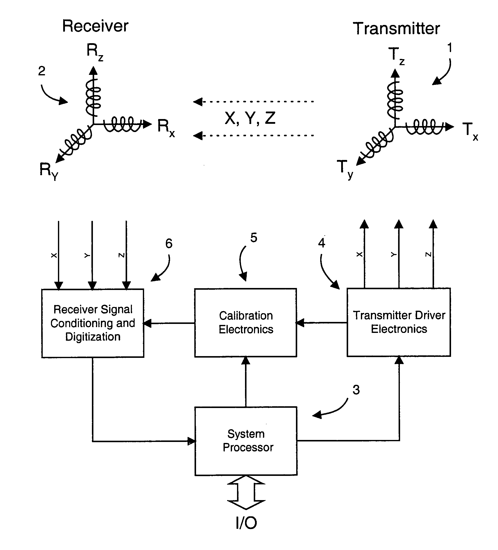
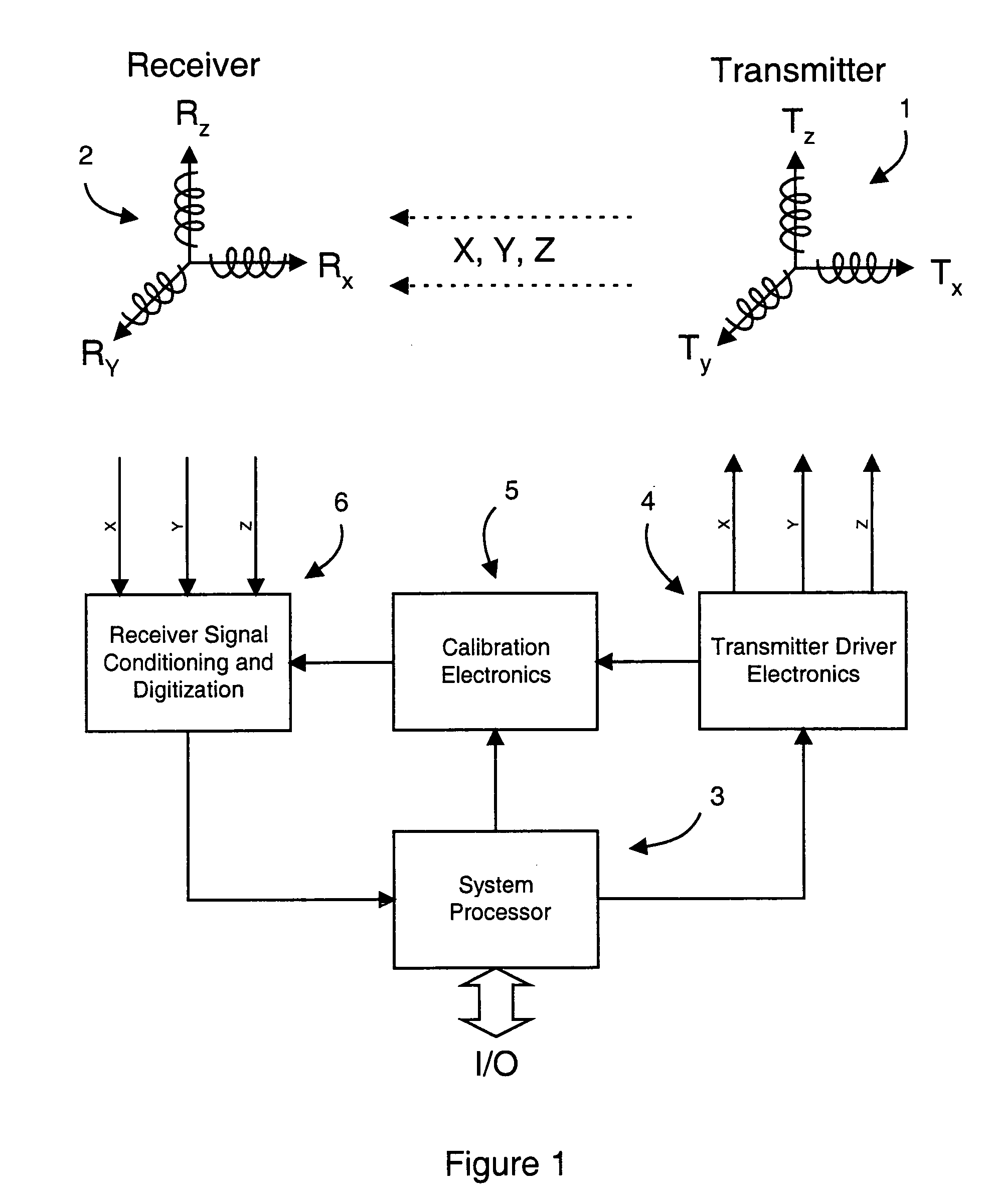
REFERENCE TO RELATED APPLICATIONS [0001] This application claims priority to U.S. Provisional Patent Ser. Nos. 60 / 603,106, filed Aug. 20, 2004 and 60 / 629,788, filed Nov. 19, 2004, the entire content of both of which are incorporated herein by reference.FIELD OF THE INVENTION [0002] This invention relates generally to AC magnetic tracking systems and, in particular, to self-training systems and inside-out and outside-in configurations providing advanced motion tracking capabilities. BACKGROUND OF THE INVENTION [0003] In classical AC magnetic tracking systems a single, static source of a three-axis field is detected by multiple sensors which are free to move about a nearby volume (FIG. 1). Systems wishing to cover greater distances can utilize a larger source driven at increasingly higher energy levels. This approach (FIG. 2) has proved difficult, however, since the magnetic near-field drops off as the third order of range from the source. That is, the signal is proportional to k B / r3...

Claims


Application Information

Patent Timeline
IPC IPC(8): G01B7/30
CPCA61B5/1127
Inventor HIGGINS, ROBERT F.JONES, HERBERT R. JR.RODGERS, ALLAN G.FARR, JAMES C.MURRY, HERSCHELL F.
Owner ALKEN INC DBA POLHEMUS
Learn More