Method And Apparatus For Synchronizing a Transmitter and Receiver in a Magnetic Tracking System

a technology of magnetic tracking system and transmitter, applied in the direction of electrical/magnetically converting sensor output, magnetic measurement, instruments, etc., can solve the problems of limiting the accuracy of such magnetic tracking system, reducing the accuracy of magnetic field detection by the tracker, and distortion of the magnetic field

Active Publication Date: 2016-01-14
PENUMBRA
View PDF5 Cites 15 Cited by
  • Summary
  • Abstract
  • Description
  • Claims
  • Application Information

AI Technical Summary

Problems solved by technology

There are a number of factors that limit the accuracy of such magnetic tracking systems.
The strength of the magnetic field between a tracking device and a base station transmitter suffers from attenuation over distance, which decreases accuracy in the detection of the magnetic field by the tracker.
Objects located between the tracking device and the base station may cause distortion in the magnetic field, particularly if those objects contain ferrous materials.
Conducting surfaces in the environment may also contain eddy currents induced by the generated magnetic field which in turn generate secondary magnetic fields that interfere with the ability of sensors to detect the source magnetic field.
Another factor is that errors in detection of the magnetic field by a receiver which cause the position and orientation of the receiver to be incorrectly determined are typically larger the farther away the receiver is from the transmitter.
Further, the error may not be linear, i.e., the error may increase faster than the distance between the receiver and the transmitter.
Still another source of ambiguity in wireless magnetic tracking systems is the magnetic field signal phases that are received by the sensor.
When the phase of the transmitted signal is unknown, the sign of the received signals is ambiguous, which can create an additional uncertainty in the location of the receiver with respect to its direction from the transmitter.
Changes in the magnetic field, error in the determination of the magnetic field and phase ambiguity all contribute to inaccurate determination of the position and orientation of a receiver relative to a transmitter in a magnetic tracking system.

Method used


Image

  • Method And Apparatus For Synchronizing a Transmitter and Receiver in a Magnetic Tracking System
  • Method And Apparatus For Synchronizing a Transmitter and Receiver in a Magnetic Tracking System
  • Method And Apparatus For Synchronizing a Transmitter and Receiver in a Magnetic Tracking System

Examples


Embodiment Construction

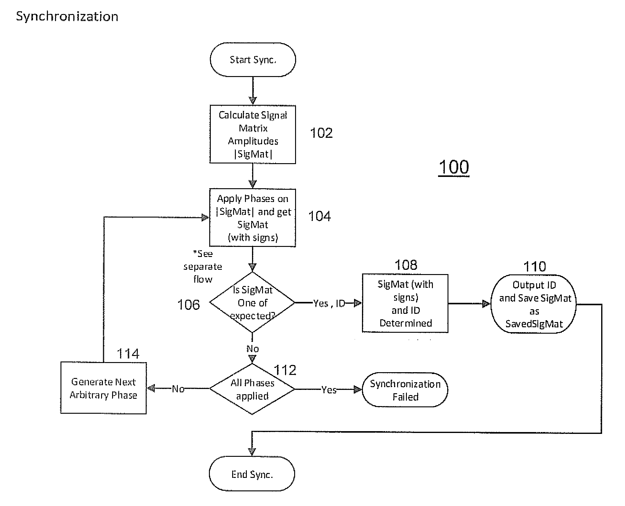
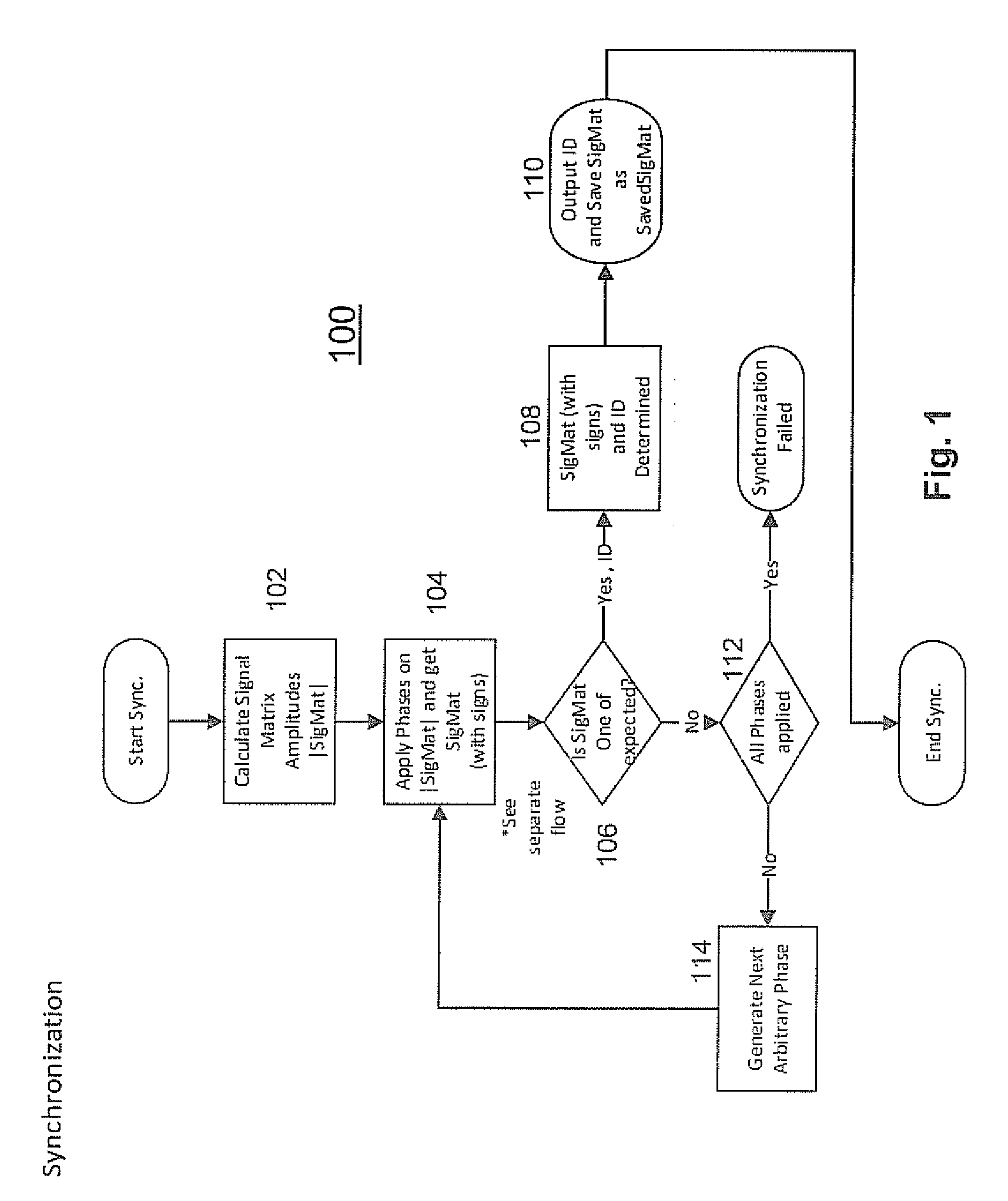
[0021]In one embodiment, a method and apparatus is disclosed for synchronizing a magnetic field transmitter and receiver to resolve phase ambiguity so that phase information for the position and orientation of the receiver may be derived and maintained. A synchronization process allows for the phase information to be initially derived based upon known information from other sources. The phase information may then be tracked and updated, assuming that there is correlation between the signals from the receiver from one measurement to the next.

[0022]In another embodiment, the synchronization process includes the use of information from an inertial measurement unit (IMU) to determine the phase information. An IMU is an electronic device that is commonly used to measure and report the velocity, orientation and gravitational forces on a device or craft, using a combination of accelerometers and gyroscopes, and sometimes even magnetometers.

[0023]In still another embodiment, information fro...


PUM


Abstract

A method and apparatus is disclosed for synchronizing a magnetic field transmitter and receiver to resolve phase ambiguity so that phase information for the position and orientation of the receiver may be derived and maintained. A synchronization process allows for the phase information to be initially derived based upon known information from other sources, and then tracked from one measurement to the next. In another embodiment, information from an inertial measurement unit (IMU) is used to determine the phase information or to correct for errors in the determination from receiver data of the position and orientation of a receiver, and prevent such errors from accumulating as the receiver moves away from a transmitter.

Description

[0001]This application claims priority to Provisional Application No. 62 / 023,750, filed Jul. 11, 2014, which is incorporated by reference herein in its entirety.FIELD OF THE INVENTION[0002]The present invention relates generally to magnetic tracking devices, and more particularly to error correction for such devices.BACKGROUND OF THE INVENTION[0003]Alternating current (AC) magnetic tracking systems typically use a method in which magnetic fields are generated and measured using a system of orthogonal coils to generate position and orientation information which is used by a computer system. One common application is tracking a user for the purpose of playing a video game or being immersed in a virtual reality world.[0004]In some prior art embodiments, a transmitter has three orthogonal coils which generate the magnetic field signal, and may be located in a fixed position, such as in a local base station, video game console or other apparatus. A receiver in a tracking device similarly...

Claims


Application Information

Patent Timeline
Patent Type & Authority Applications(United States)
IPC IPC(8): G01D5/20G01R33/00
CPCG01R33/0023G01D5/20G01C25/00G01V7/00
Inventor PEDROTTI, OWEN WALTERZUR, ODED Y.
Owner PENUMBRA
Why Eureka
Try Eureka