Optical compensation of cover glass-air gap-display stack for high ambient lighting

a technology of optical compensation and cover glass, applied in the field of flat (commercial off the shelf) cots display technologies, can solve the problems of low yield and long-lead production schedule, undesired thickness of “ruggedized” flat panel displays, and inability to meet user requirements. the effect of minimization of reflectan

Active Publication Date: 2005-12-29
NORTHROP GRUMMAN SYST CORP +1
View PDF4 Cites 104 Cited by
  • Summary
  • Abstract
  • Description
  • Claims
  • Application Information

AI Technical Summary

Benefits of technology

[0003] The present invention is directed to apparatus and methods relating to display stacks wherein one or more index matching layers are utilized to minimize reflectance at the boundaries of otherwise adjacent layers. More particularly, the present invention is directed to methods and apparatus relating to a multilayer display stack comprising a glass layer, a first index matching layer, a first intermediate layer, a second index matching layer, a second intermediate layer, and a light emitting or light transmitting display panel wherein: the glass layer, first index matching layer, first intermedia...

Problems solved by technology

“Ruggedized” flat panel displays are undesirably thick, heavy, and costly.
In addition, significant process control and producibility problems lead to low yield and long-lead production ...

Method used


Image

  • Optical compensation of cover glass-air gap-display stack for high ambient lighting
  • Optical compensation of cover glass-air gap-display stack for high ambient lighting

Examples


Embodiment Construction

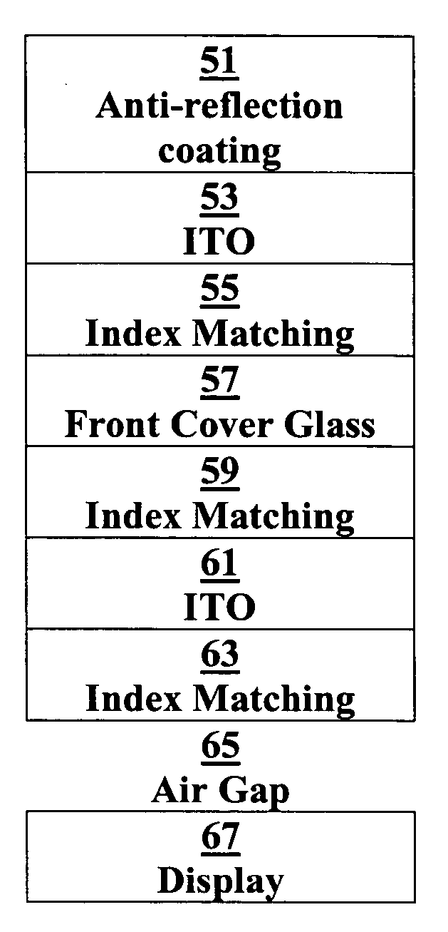
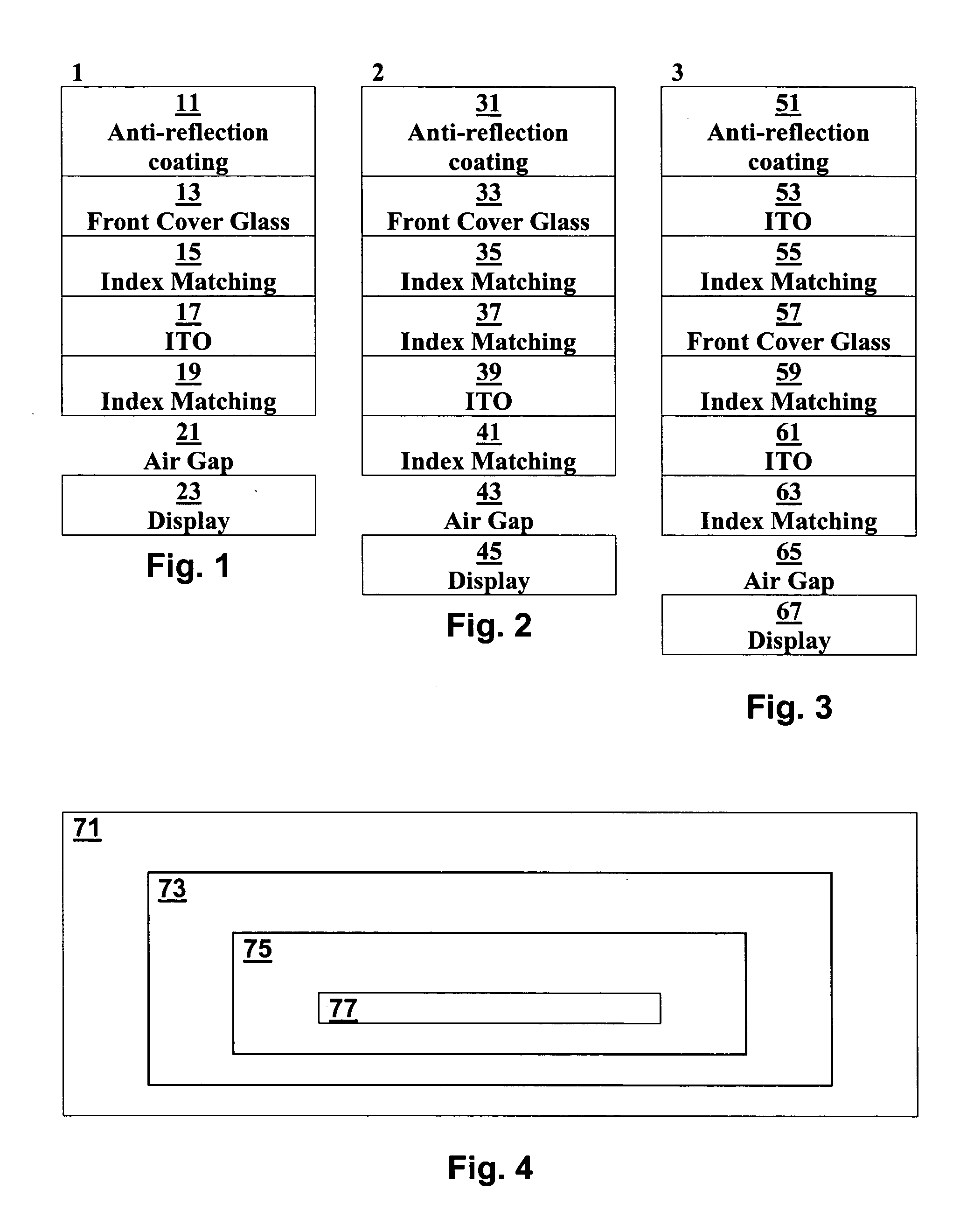
[0009] Reference will now be made to the preferred embodiments of the invention, examples of which are illustrated in the accompanying drawings. While the invention will be described in conjunction with the preferred embodiments, it will be understood that these embodiments are not intended to limit the invention. On the contrary, the invention is intended to cover alternatives, modifications and equivalents, which may be included within the spirit and scope of the invention as defined by the appended claims. In the following detailed description, numerous specific details are set forth in order to provide a thorough understanding of the present invention. However, it will be understood by one of ordinary skill in the art that the present invention may be practiced without these specific details. In other instances, well known methods, procedures, components, and circuits have not been described in detail so as not to unnecessarily obscure the important aspects of the present invent...


PUM

PropertyMeasurementUnit
Thicknessaaaaaaaaaa
Thicknessaaaaaaaaaa
Electrical conductivityaaaaaaaaaa

Abstract

Apparatus and methods relating to display stacks wherein one or more index matching layers are utilized to minimize reflectance at the boundaries of otherwise adjacent layers. More particularly, the present invention is directed to methods and apparatus relating to a multilayer display stack comprising a glass layer, a first index matching layer, a first intermediate layer, a second index matching layer, a second intermediate layer, and a light emitting display panel wherein: the glass layer, first index matching layer, first intermediate layer, second index matching layer, and second intermediate layer are each transparent or translucent, and comprise an index of refraction; the index of refraction of the first index matching layer is between the index of refraction of the glass layer and the first intermediate layer; and the index of refraction of the second index matching layer is between the index of refraction of the first intermediate layer and the second intermediate layer. Alternative embodiments may comprise additional index matching layers, additional non-index matching layers, as well as layers other than those described herein.

Description

FIELD OF THE INVENTION [0001] The present invention relates generally to flat (Commercial-Off-The-Shelf) COTS display technologies adapted and housed in assemblies for military and other severe environments, apparatus incorporating such assemblies, and methods for forming and using such assemblies. BACKGROUND OF THE INVENTION [0002] Used in the context of flat panel displays, the term “ruggedized” typically means multiple layers of front glass, diffusers, polarizers, heater glass, and other layers bonded together with the flat panel display. Multiple layers of epoxy, adhesive, optical compounds, and other bonding materials are used to attach the layers. “Ruggedized” flat panel displays are undesirably thick, heavy, and costly. In addition, significant process control and producibility problems lead to low yield and long-lead production schedules. In addition, “ruggedized” flat panel displays often do not satisfactorily meet user requirements due to design problems inherent to the co...

Claims


Application Information

Patent Timeline
IPC IPC(8): G02B1/10G02B1/11G02F1/1335
CPCG02B1/10G02F1/133502G02B1/11G02F1/13
Inventor SAXENA, RAGINIBONG, BAN S.HAVELKA, STEVEN E.LOO, THOMASSCAPPATICCI, ALBERT V.
Owner NORTHROP GRUMMAN SYST CORP
Why Eureka
Try Eureka