Information recording medium and information recording/reproducing apparatus to increase recording density

a technology of information recording and information, applied in the field of information recording medium and information recording/reproducing apparatus, can solve the problems of large light reflectance, inability to increase the recording density of information, and inability to uniform light distribution at the entrance pupil, etc., to achieve the effect of reducing light reflectan

Inactive Publication Date: 2006-10-24
HUANG HUADAO +1
View PDF14 Cites 0 Cited by
  • Summary
  • Abstract
  • Description
  • Claims
  • Application Information

AI Technical Summary

Benefits of technology

[0020]A thickness of the thin film layer may be set so as to minimize a substantial reflectance for light, which enters the first surface of the transparent substrate, while being converged, at an incident angle in the range of 0° to the maximum possible incident angle and is reflected by the first surface of the transparent substrate.
[0022]The thickness of the thin film layer may be set so as to minimize the reflectance for light, which enters the first surface of the transparent substrate at the maximum possible incident angle and is reflected by the first surface of the transparent substrate.

Problems solved by technology

However, in the case of a conventional optical disc, when the numerical aperture NA of the objective lens is increased, the maximum possible incident angle of light incident on a surface of the optical disc becomes large, and thus a reflectance for the light becomes large, so that light distribution at the entrance pupil cannot be uniform.
As described above, with a conventional optical disc, the light spot cannot be sufficiently small, and thus it is not possible to increase a recording density of information.

Method used


Image

  • Information recording medium and information recording/reproducing apparatus to increase recording density
  • Information recording medium and information recording/reproducing apparatus to increase recording density
  • Information recording medium and information recording/reproducing apparatus to increase recording density

Examples


example 1

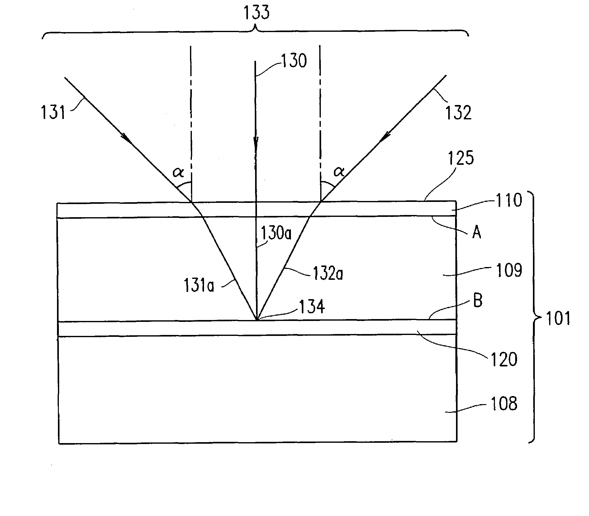
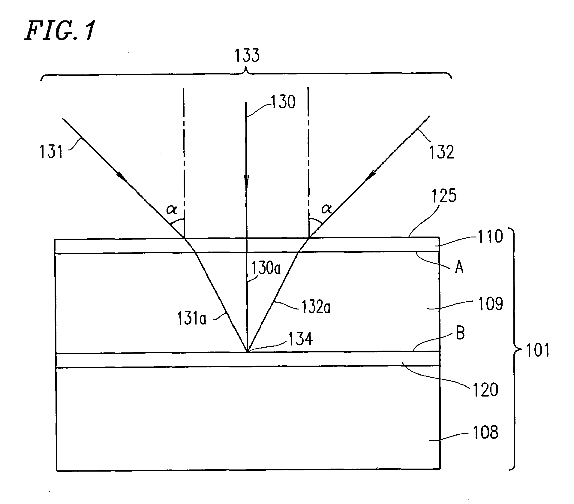
[0043]FIG. 1 is a cross-sectional view of an optical disc 101 (an information recording medium) according to Example 1 of the present invention. The optical disc 101 includes: a transparent substrate 109 having a surface A (a first surface) and a surface B (a second surface) opposite to the surface A; a thin film layer 110 provided on the surface A of the transparent substrate 109; and an information recording layer 120 provided on the surface B of the transparent substrate 109. All of these elements are held on a base 108.

[0044]The information recording layer 120 may have any configuration capable of retaining information.

[0045]FIG. 1 shows that light (lights 130, 131, and 132) enters the surface A of the transparent substrate 109 at an angle in the range of 0° to α (the maximum possible incident angle). Portions of the lights 130, 131, and 132 transmitted through the transparent substrate 109 (corresponding to lights 130a, 131a, and 132a) are converged on the information recording...

example 2

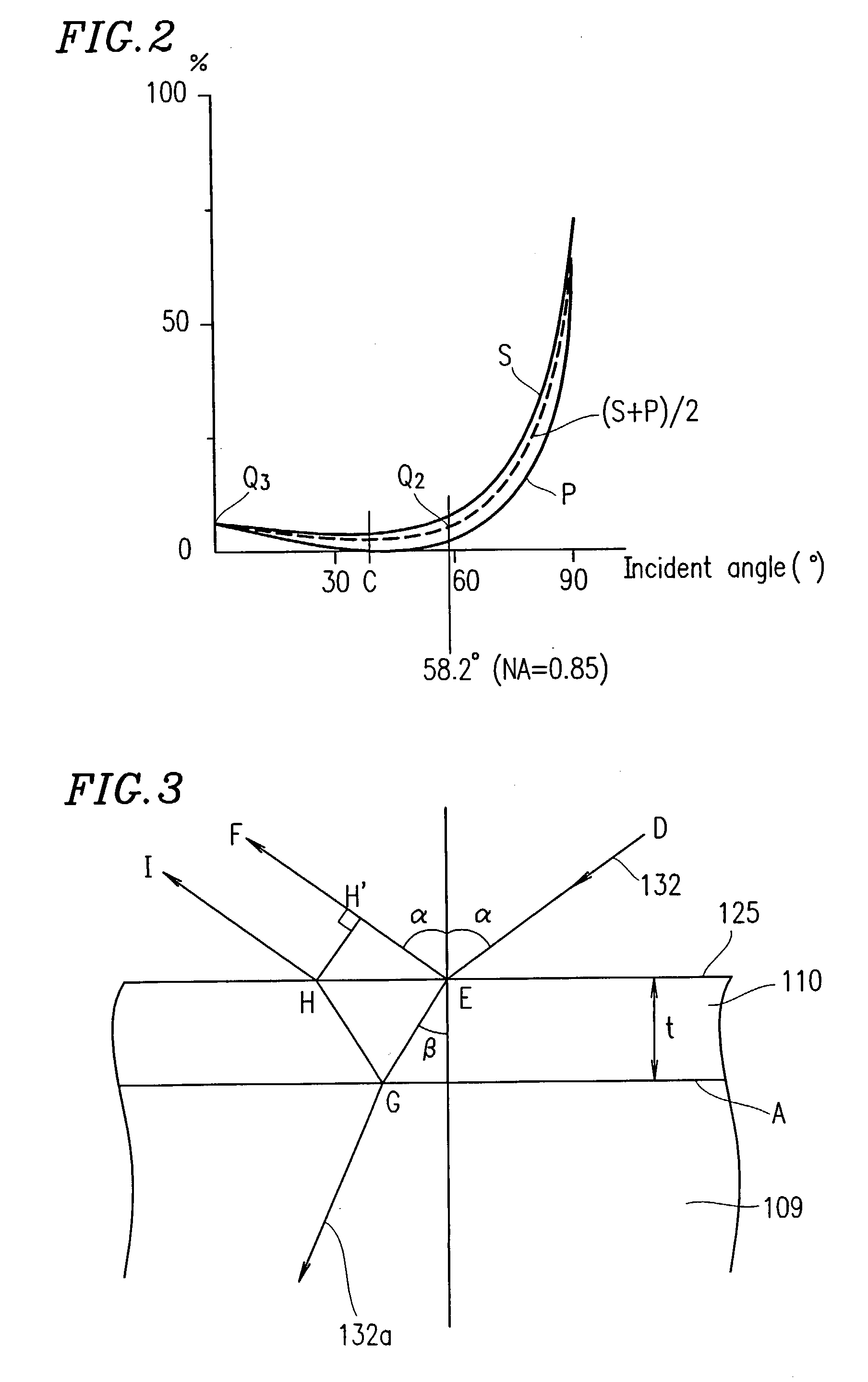
[0075]In Example 1, the thin film layer 110 functions as a reflectance reduction means for reducing a reflectance for light which enters the surface A of the transparent substrate 109 at the maximum possible incident angle α and is reflected by the surface A, while, in Example 2, another example of the reflectance reduction means is described.

[0076]FIG. 4A is a cross-sectional view of an optical disc 201 (an information recording medium) according to Example 2 of the present invention. The optical disc 201 includes: a transparent substrate 209 having a surface A (a first surface) and a surface B (a second surface) opposite to the surface A; a plurality of structures 203 provided on the surface A of the transparent substrate 209; and an information recording layer 220 provided on the surface B of the transparent substrate 209. All of these elements may be held on a base (not shown).

[0077]FIG. 4A shows that light (lights 130, 131, and 132) enters the surface A of the transparent subst...

example 3

[0092]Example 3 is described with reference to an information recording / reproducing apparatus including the optical disc 101 (FIG. 1) or optical disc 201 (FIG. 4A) described above in Example 1.

[0093]FIG. 5 illustrates a configuration of an information recording / reproducing apparatus 401 according to Example 3 of the present invention. The information recording / reproducing apparatus 401 includes an optical disc 101 and an optical head 402. The information recording / reproducing apparatus 401 records information to the optical disc 101 or reproduces information recorded on the optical disc 101. The optical disc 101 is the same as that described above in conjunction with Example 1 of the present invention and with reference to FIG. 1.

[0094]The optical head 402 includes a radiation source 104, a beam splitter 102, a collimating lens 103, a combined objective lens 105, a hologram 111, and a photodetector 112. The combined objective lens 105 includes a cemented lens 106 and a front objecti...


PUM

PropertyMeasurementUnit
incident angleaaaaaaaaaa
emission wavelengthaaaaaaaaaa

Abstract

An information recording medium 101 includes: a transparent substrate 109 having a first surface A and a second surface B opposite to the first surface A; reflectance reduction means 110 provided on the first surface A of the transparent substrate 109; and an information recording layer 120 provided on the second surface B of the transparent substrate 109.

Description

TECHNICAL FIELD[0001]The present invention relates to an information recording medium and an information recording / reproducing apparatus.BACKGROUND ART[0002]Examples of conventionally known optical discs to / from which information is recorded / reproduced include CDs, DVDs, etc. When recording / reproducing information to / from a conventional optical disc, an incident angle of light incident on a surface of the optical disc does not have a great value.[0003]FIG. 7 illustrates an exemplary configuration including a conventional optical disc 508 and an optical head 513 for recording / reproducing information to / from the optical disc 508. The optical head 513 includes a radiation source 501, a beam splitter 502, a collimating lens 503, an objective lens 506, a hologram 511, and a photodetector 512.[0004]When reproducing information recorded on the optical disc 508, a light beam emitted by the radiation source 501 is transmitted through the beam splitter 502 and rendered into a parallel beam by...

Claims


Application Information

Patent Timeline
Patent Type & Authority Patents(United States)
IPC IPC(8): G11B7/00G11B7/135G11B7/24G11B7/252G11B7/253G11B7/2531G11B7/2533G11B7/2534G11B7/254G11B7/2542
CPCG11B7/1374G11B7/13922G11B7/24G11B7/252G11B7/2531G11B7/2533G11B7/2534G11B7/2542G11B2007/13727
Inventor SAIMI, TETSUOARAI, AKIHIRONAKAMURA, TOHRU
Owner HUANG HUADAO
Why Eureka
Try Eureka