Optical time division multiplexer

a time division multiplexer and optical signal technology, applied in the field of optical time division multiplexers, can solve the problems of compromising the speed at which the tdm switches or the quality of the outputted signal

Inactive Publication Date: 2005-12-29
LUCENT TECH INC
View PDF5 Cites 8 Cited by
  • Summary
  • Abstract
  • Description
  • Claims
  • Application Information

AI Technical Summary

Benefits of technology

[0009] The present invention involves the recognition that coupling the speed of a time division multiplexer (TDM) with its quality (i.e., wavelength stability), retards the overall performance of the TDM. In other words, since outputting a stable wavelength signal and switching the signal quickly are functions which have competing objectives—quality versus speed, using a wavelength-tunable device to perform both the functions either compromises the speed at which the TDM switches or the quality of the outputted signal.

Problems solved by technology

In other words, since outputting a stable wavelength signal and switching the signal quickly are functions which have competing objectives—quality versus speed, using a wavelength-tunable device to perform both the functions either compromises the speed at which the TDM switches or the quality of the outputted signal.

Method used


Image

  • Optical time division multiplexer
  • Optical time division multiplexer
  • Optical time division multiplexer

Examples


Embodiment Construction

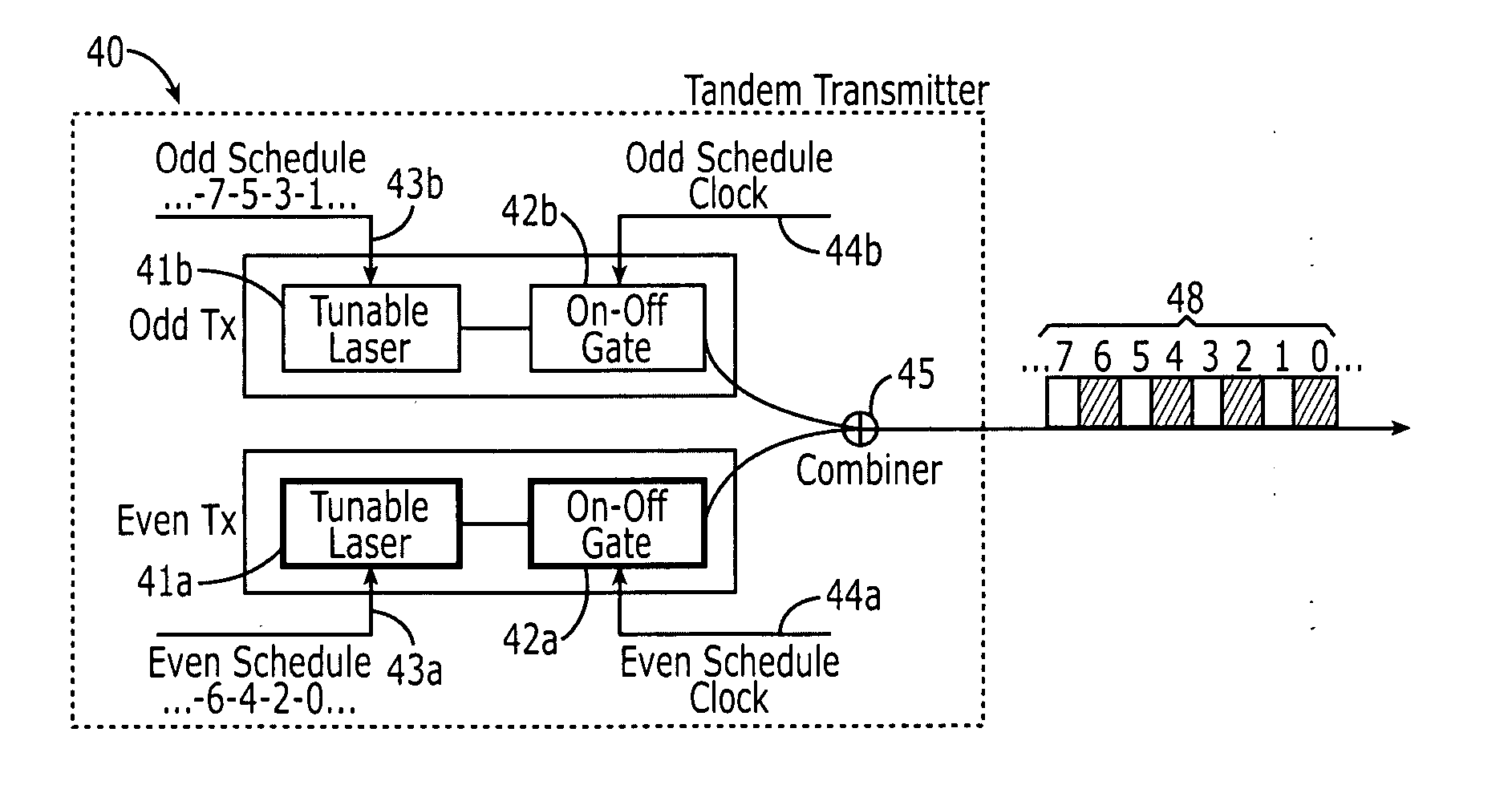
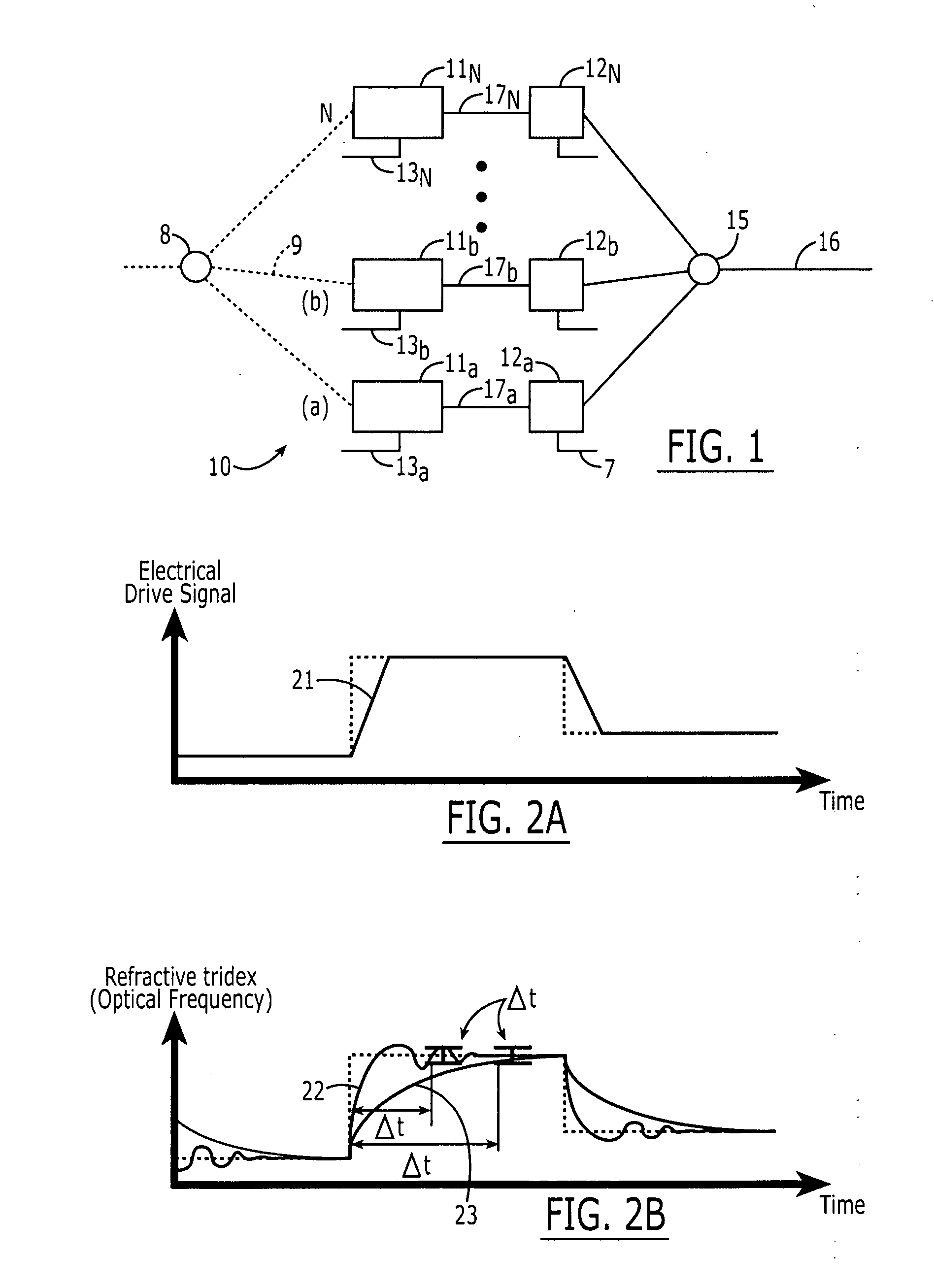
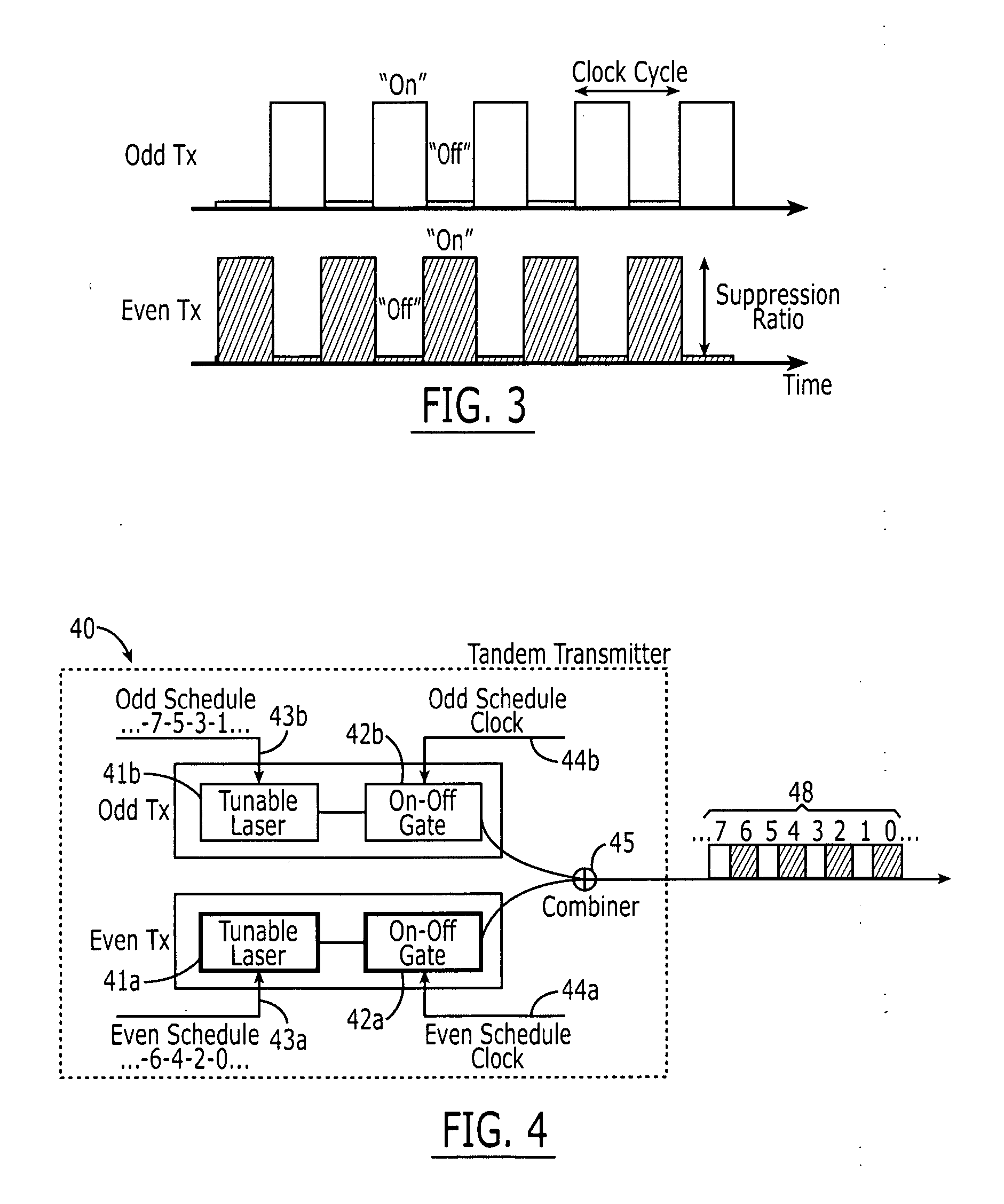
[0018] Referring to FIG. 1, a preferred embodiment of an N:1 time division multiplexer (TDM) 10 of the present invention is shown. The TDM 10 comprises N sets of wavelength-tunable devices 11a, 11b . . . 11N in tandem with gates 12a, 12b . . . 12N in which N is 2 or greater. Each wavelength-tunable device 11a, 11b . . . 11N is adapted to output a signal 17a, 17b . . . 17N having a wavelength which is adjustable in response to a change signal 13a, 13b . . . 13N, respectively. One on-off gate is coupled to the output of each wavelength-tunable device. For example, as shown in FIG. 1, gate 12a is coupled to the output of wavelength-tunable device 11a, and gate 12b is coupled to the output of wavelength-tunable device 12a. When a gate is on, the signal of its respective wavelength-tunable device passes through, and, when it is off, the signal of its respective wavelength-tunable device does not pass through. The gates are configured such that a gate is switched off when its respective w...


PUM


Abstract

A TDM comprising: (a) at least two wavelength-tunable devices for outputting a signal, each wavelength-tunable device being adapted to change signal wavelength in response to a change signal; (b) a plurality of on-off gates, one on-off gate being coupled to the output of each wavelength-tunable device such that, when a gate is on, the signal of its respective wavelength-tunable device passes through, and, when it is off, the signal of its respective wavelength-tunable device does not pass through, the gates being configured such that a gate is switched off when its respective wavelength-tunable device receives a change signal, and, when one gate is turned off, another gate is turned on; and (c) a combiner coupled to the outputs of all the gates for combining the outputs on a single transmission line.

Description

FIELD OF INVENTION [0001] This invention relates generally to a time division multiplexer of optical signals and, more specifically, to an optical time division multiplexer using wavelength-tunable devices such as tunable lasers and filters. BACKGROUND OF INVENTION [0002] Future generations of high-capacity packet switches, cross-connects and other telecommunication apparatus will likely rely on internal optical switching technologies to overcome current limitations facing high-speed and high-capacity electronic switching, routing and transport. Additionally, there are numerous other applications for optical wavelength switching technologies that have been discussed recently, including, for example, future optical metro or access networks, optical memory access, optical super-computing, and optical processing in general. A common factor among these applications is that a particular function (e.g. port switching, packet routing, memory access, etc.) depends on the wavelength of an op...

Claims


Application Information

Patent Timeline
Patent Type & Authority Applications(United States)
IPC IPC(8): H04J4/00H04J14/08
CPCH04J14/086
Inventor DUELK, MARCUS
Owner LUCENT TECH INC
Why Eureka
Try Eureka