Flexible control and status architecture for optical modules

a technology of optical modules and status signals, applied in the direction of electromagnetic transmission, electrical apparatus, electromagnetic transceivers, etc., can solve the problems of insufficient flexibility of c&s interface, long transponder development cycle, and high transponder cos

Inactive Publication Date: 2005-12-29
LUMENTUM OPERATIONS LLC
View PDF5 Cites 52 Cited by
  • Summary
  • Abstract
  • Description
  • Claims
  • Application Information

AI Technical Summary

Benefits of technology

[0016] In another aspect of the present invention, the optoelectronic module provided by the invention is a transponder module for transmitting and receiving optical signals through the fiber-optic link, wherein the functional hardware comprises: electro-optic generating means for generating an output optical signal; opto-electronic receiving means for receiving an input optical signal and for converting thereof into a received electrical signal; electrical multiplexing means for multiplexing a plurality of input electrical data signals received from the host device into a

Problems solved by technology

These systems typically include complex equipment that aggregates multiple information streams from a plurality of customers or customer sites into high data rate signals, and transmits these high data rate signals over an optical fiber of a fiber-optic link.
Modem developments in optical communication networks impose contradictory requirements on the optoelectronic modules they employ.
Furthermore, due to the proprietary nature of telecommunication systems used in optical networks, different customers often have differing requirements for particular aspects of the

Method used


Image

  • Flexible control and status architecture for optical modules
  • Flexible control and status architecture for optical modules
  • Flexible control and status architecture for optical modules

Examples


Embodiment Construction

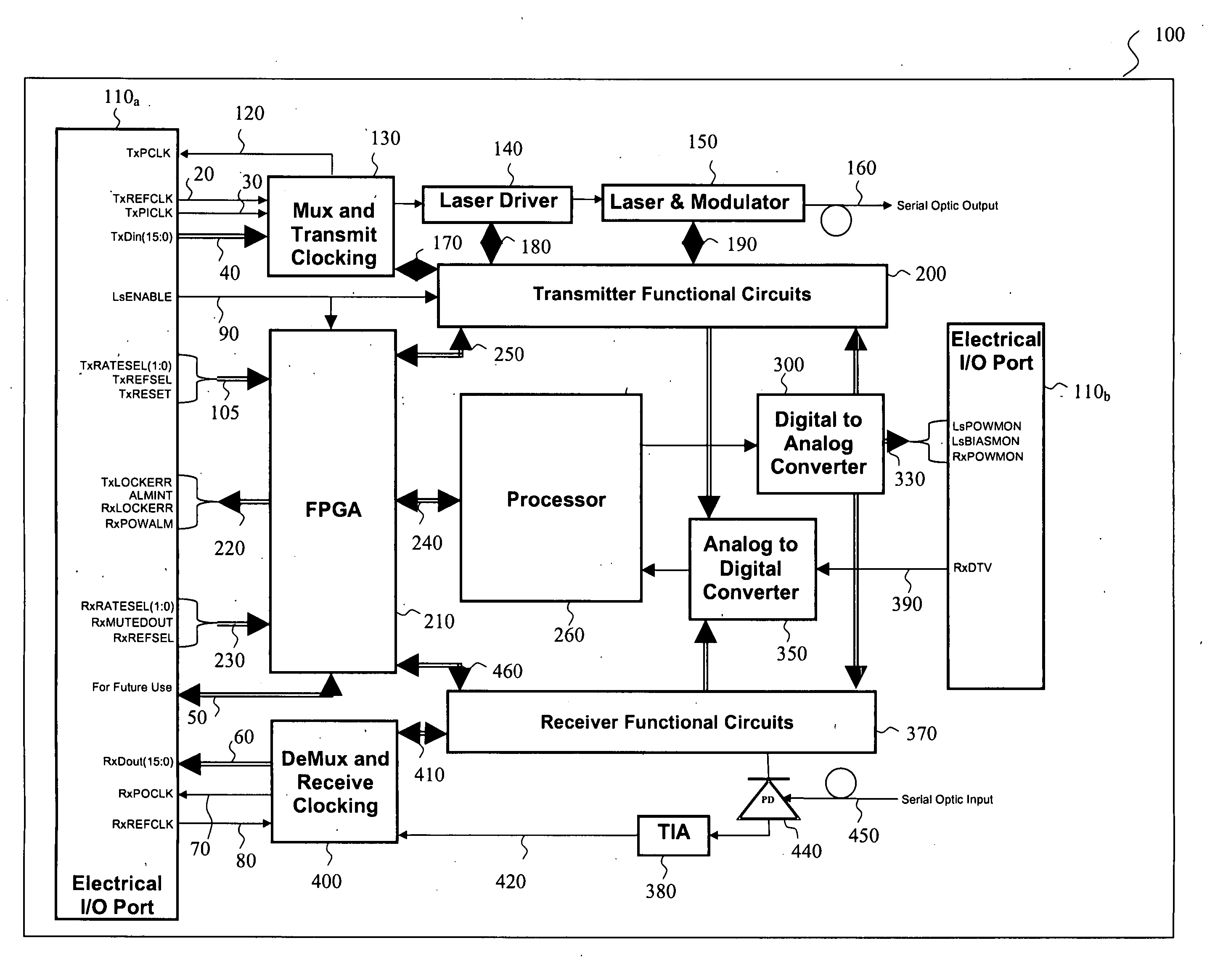
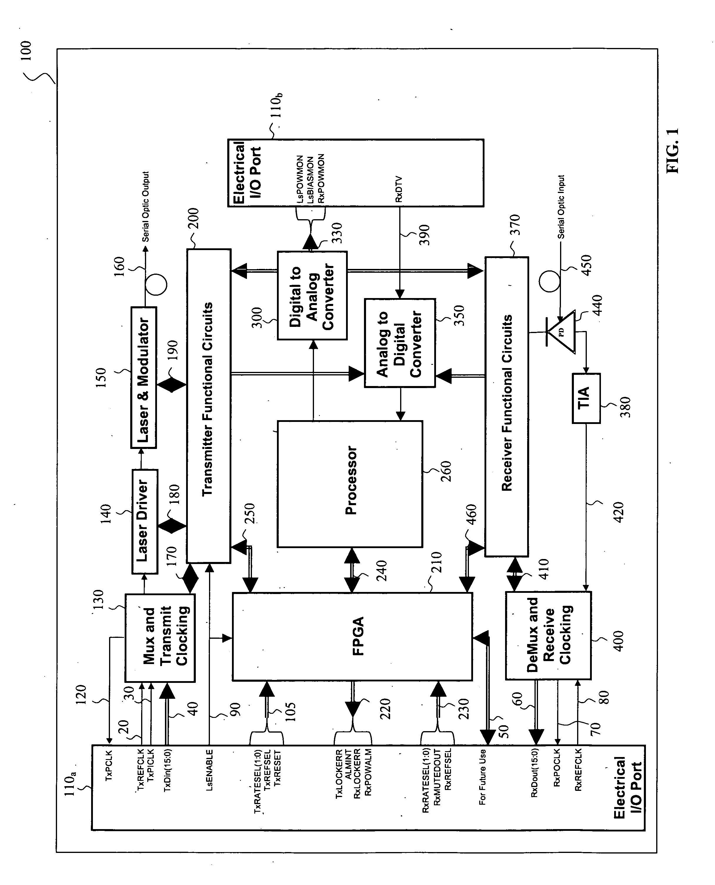
[0023] In general, the present invention relates to optoelectronic modules having a digital control and status (C&S) interface, such as modules used in optical communications for transmitting and receiving optical signals through a fiber-optic link, which are commonly known as optical transponders or optical transceivers.

[0024] In operation, the modules are connected to and are in communication with an external host device. The external host device can be a computer, a test station, a telecommunication equipment shelf, a line card of an optical communication system, or another appropriate host device having a compatible port.

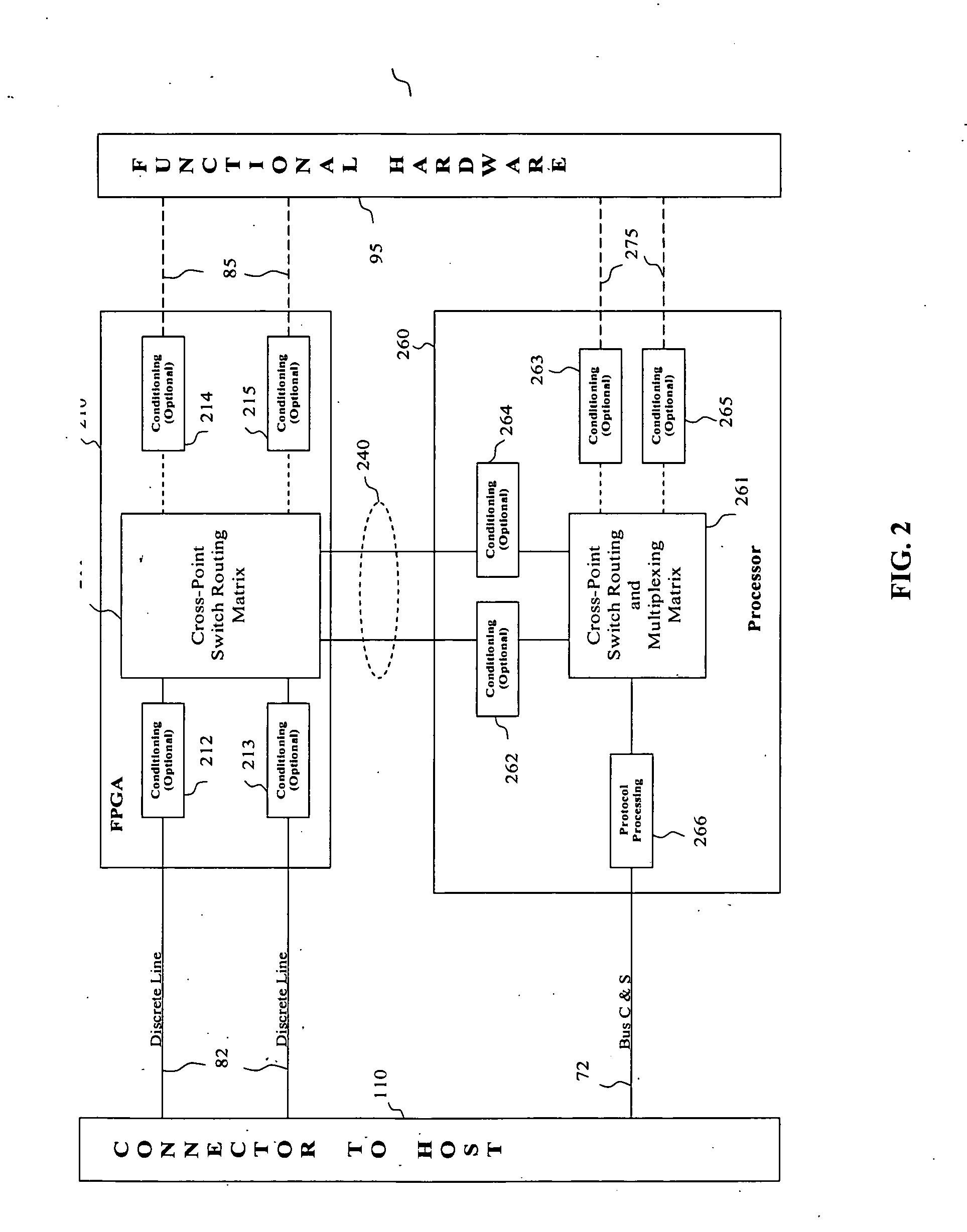
[0025] In the context of the present invention, the words “control and status interface” or “C&S interface” of a module are used to mean a plurality of digital control and status signals that in operation are exchanged between the module and an external host device, in combination with hardware connection means of the module for providing electrical connection...


PUM


Abstract

The invention relates to optoelectronic modules for generating and/or receiving optical signals for use in fiber-optic communication systems, such as optical transponders or transceivers, having a reconfigurable control and status (C&S) interface with a host device. The optoelectronic module includes an electrical multi-pin host connector having a plurality of pins for communicating a plurality of digital C&S signals between the host and the module, functional hardware responsive to the digital control signals and comprising sensing means for generating digital status signals, and processing means formed by an FPGA and a processor for processing the digital C&S signals. The FPGA is disposed in communications paths between the host connector on one side, and the functional hardware and the processor on the other side, and programmed for routing each of the discrete C&S signals between the C&S pins of the host connector and the processor, and between the C&S pins and the functional hardware, thereby providing reconfigurability of said routing by downloading a different set of FPGA instructions.

Description

CROSS-REFERENCE TO RELATED APPLICATIONS [0001] The present invention claims priority from U.S. Patent Application No. 60 / 583,587 filed Jun. 28, 2004 entitled “Flexible digital control and status architecture for optical modules”, which is incorporated herein by reference.TECHNICAL FIELD [0002] The present invention relates to control and status signaling architecture of optical modules for fiber-optic communication systems. BACKGROUND OF THE INVENTION [0003] Fiber-optic communication systems are widely used for transmitting a high volume of voice, video and data information over medium to large distances. These systems typically include complex equipment that aggregates multiple information streams from a plurality of customers or customer sites into high data rate signals, and transmits these high data rate signals over an optical fiber of a fiber-optic link. [0004] To be transmitted over an optical link, the data has to be first converted from its original electrical format to an ...

Claims


Application Information

Patent Timeline
IPC IPC(8): H04B10/00H04B10/24
CPCH04B10/40
Inventor PIERCE, JAY J.KANAGY, DARRELSCHNEIDER, DAVIDZUHLKE, CHRISTOPHER A.
Owner LUMENTUM OPERATIONS LLC
Why Eureka
Try Eureka