
Data cleaning with an asynchronous reference clock

a data cleaning and reference clock technology, applied in the field of integrated circuits, can solve the problems of affecting the reach of the data transmission device, affecting the accuracy of data transmission devices, so as to reduce the jitter generation of data transmission devices

Active Publication Date: 2006-10-05
SKYWORKS SOLUTIONS INC
View PDF21 Cites 30 Cited by
  • Summary
  • Abstract
  • Description
  • Claims
  • Application Information

AI Technical Summary

Benefits of technology

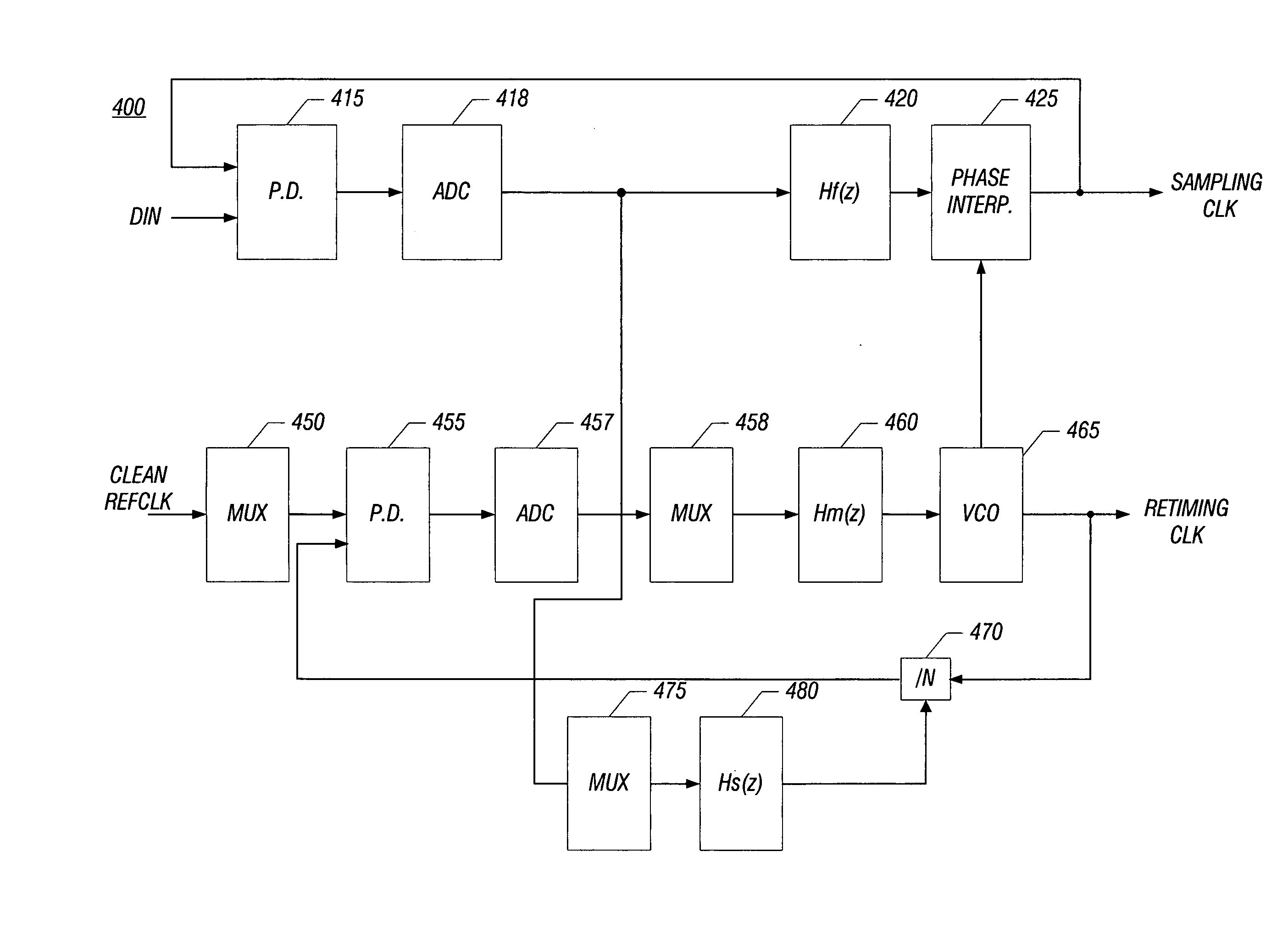
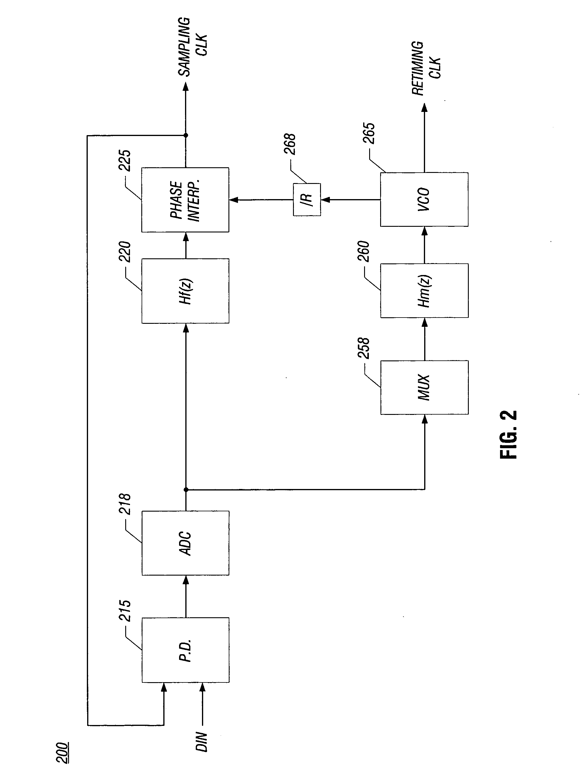
[0009] In various embodiments, the present invention may provide independent setting of jitter tolerance and jitter transfer levels, and further may reduce jitter generation of a data transmission device, such as a clock and data recovery (CDR) circuit or the like. An architecture in accordance with one embodiment may provide for reconfigurability of a circuit for use in various applications, for example, at different frequencies and with different reference clock sources (or without a reference clock source). Further, a reference clock (if present) may be generated using a low-cost arbitrary frequency crystal, in some embodiments.

Problems solved by technology

Jitter tolerance is defined in terms of an applied jitter component whose amplitude, when applied to a system input, causes a certain level of degradation in error performance (e.g., bit error rate).
However, design tradeoffs exist that frustrate reaching this ideal.
As a result, limited clock cleaning opportunities exist in a CDR, as the CDR must operate at the same jitter tolerance and jitter transfer levels.
However, an external clock cleaning module consumes board space and increases expense.
Furthermore, the clock cleaning module or crystal oscillator typically does not support multiple clock frequencies.
To support multiple frequency operations, the use of multiple oscillators requires additional board space, increasing size and cost.

Method used


Image

  • Data cleaning with an asynchronous reference clock
  • Data cleaning with an asynchronous reference clock
  • Data cleaning with an asynchronous reference clock

Examples


Embodiment Construction

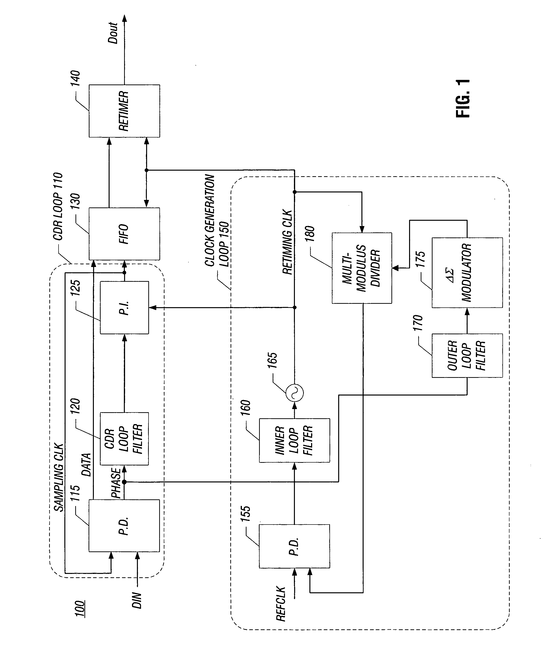
[0019] Referring now to FIG. 1, shown is a block diagram of a clock and data recovery (CDR) circuit in accordance with one embodiment of the present invention. As shown in FIG. 1, CDR 100 may be used to recover data from an incoming signal (Din) and further to recover a timing signal from the incoming signal. As an example, the incoming data may be high-speed serial data input at high data rates. A sampling clock is recovered from the incoming signal and is used to recover the data. The data is then sent out of CDR 100 as an output data signal (Dout). While not shown in FIG. 1, it is to be understood that CDR 100 may also output a clock signal (i.e., a retiming clock signal).

[0020] More specifically, as shown in FIG. 1, a CDR loop 110 recovers data according to a sampling clock, while a separate clock generation loop 150 generates a retiming clock based on phase information from CDR loop 110 and / or a reference clock provided to clock generation loop 150. The reference clock may be ...


PUM


Abstract

Embodiments of the present invention may provide for independent setting of jitter tolerance and jitter transfer levels, and reduced jitter generation of a data transmission device, such as a clock and data recovery (CDR) circuit or the like. An architecture may provide for reconfigurability of a circuit for use in various applications. The architecture may include a multi-loop structure, such as a tri-loop structure.

Description

FIELD OF THE INVENTION [0001] The present invention relates to integrated circuits, and more specifically to integrated circuits used in data communication. BACKGROUND [0002] Digital communication systems are used to transmit data, often at high speeds and over long distances. At a receiving end, a circuit can be used to recover data along with a clock signal embedded in an incoming data stream. Such circuits are generally known as clock and data recovery (CDR) circuits, which recover an embedded clock and retime received data to the recovered clock. Typically, a phase-locked loop (PLL) is used to perform the clock recovery operation. [0003] For many reasons, jitter, which is a fluctuation in the extracted clock signal from a constant rate, can occur. Jitter is to be controlled to reduce performance degradation, and some communication protocols include specifications as to allowable amounts of jitter. Different measures are used to characterize jitter within a system. Measures of ji...

Claims


Application Information

Patent Timeline
Patent Type & Authority Applications(United States)
IPC IPC(8): H04L7/00
CPCH03L7/07H03L7/0814H04L7/005H03L7/1976H04L7/033H03L7/197
Inventor ELDREDGE, ADAM B.HUANG, YUNTENG
Owner SKYWORKS SOLUTIONS INC
Learn More