Field programmable filter array

a filter array and field technology, applied in the field of tunable filters, can solve problems such as wireless systems, corrupt receiver capabilities, and problems, and achieve the effects of high spectral isolation and reconfigurability, increasing the speed and performance of wireless systems, and improving the reliability of receivers

Inactive Publication Date: 2014-03-04
PURDUE RES FOUND INC
View PDF3 Cites 23 Cited by
  • Summary
  • Abstract
  • Description
  • Claims
  • Application Information

AI Technical Summary

Benefits of technology

[0009]Certain embodiments of the present invention provide a concurrent transmission method with high levels of spectral isolation, i.e., isolation between different tunable frequencies, effective to allow for simultaneous operation of transmitters and receivers, increasing the speed and performance of wireless systems. In one embodiment, the isolation carves out regions of the spectrum that protect very narrow spectral bands in which wireless systems (radar, communications, etc.) can simultaneously operate even when a high power system is nearby as is the case in a typical jamming scenario. Intermodulation products of the interferers that fall within the receive band can be notched out with a bandstop filter in the transmitter. A bandpass filter in the receiver protects the band of interest from the interference, both co-site and external.
[0010]One embodiment of the invention is a field programmable filter array with high spectral isolation and reconfigurability. The filter array comprises a bank of resonators which can be programmed at will and on the fly to give any type of filtering response required, e.g., switching between bandstop and bandpass configurations.

Problems solved by technology

Problems exist with wireless systems in the presence of high power interferers such as are encountered in electronic warfare.
High power interferers can cause an RF receive chain to saturate or cause an A / D converter to overflow, corrupting the capability of the receiver.
Many systems are currently not able to work in the presence of high power transmitters, and co-site interference is a common problem.
Traditional time-duplexing techniques limit the performance of systems as they attempt to share spectrum.
Transmissions can be coordinated such that there is only reception when a transmitter is turned off, but this severely limits capacity.

Method used


Image

  • Field programmable filter array
  • Field programmable filter array
  • Field programmable filter array

Examples


Embodiment Construction

[0032]For the purpose of promoting an understanding of the principles of the invention, reference will now be made to the embodiments illustrated in the drawings and specific language will be used to describe the same. It will nevertheless be understood that no limitation of the scope of the invention is thereby intended, such alterations and further modifications in the illustrated device and such further applications of the principles of the invention as illustrated therein being contemplated as would normally occur to one skilled in the art to which the invention relates.

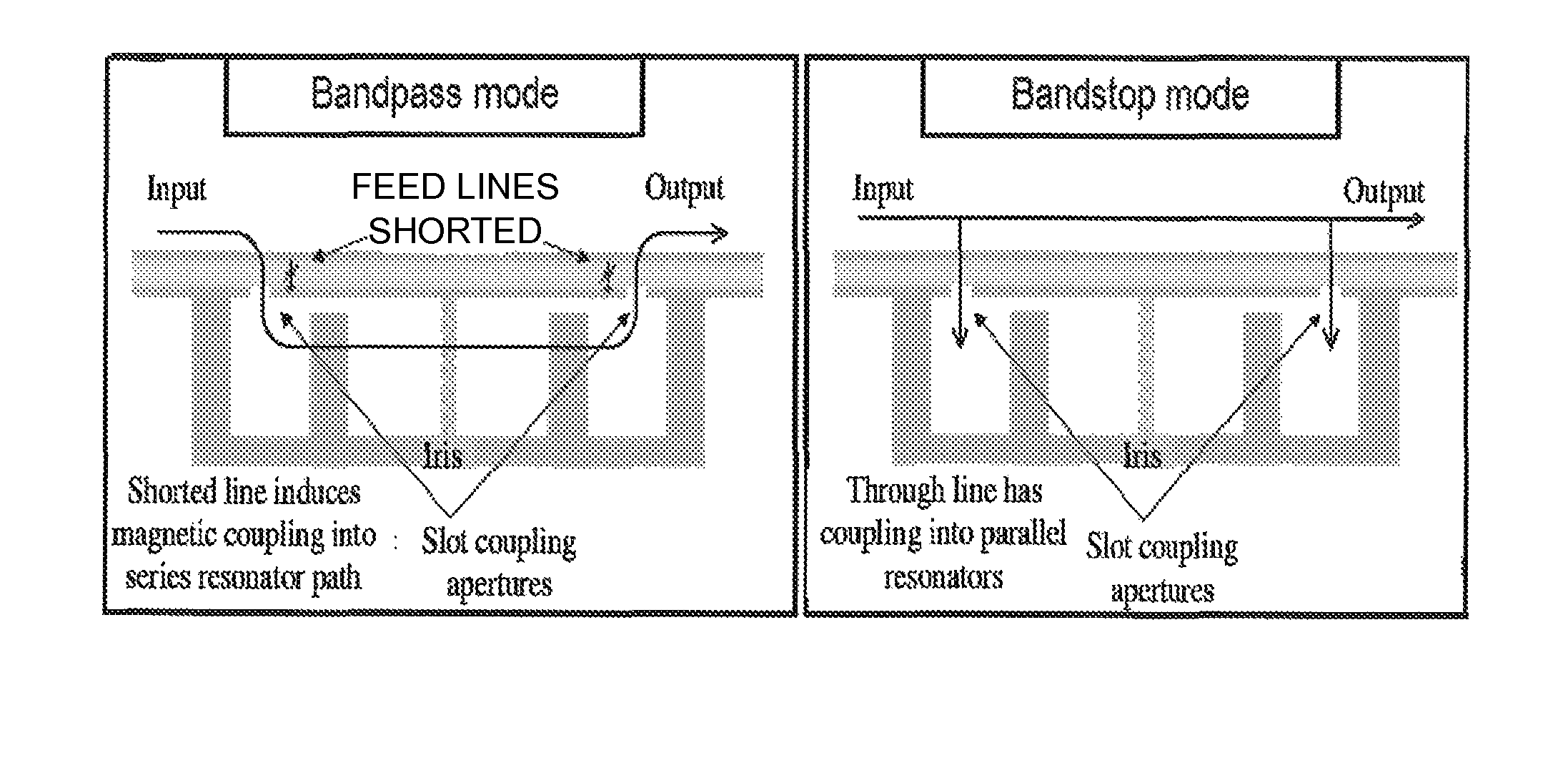
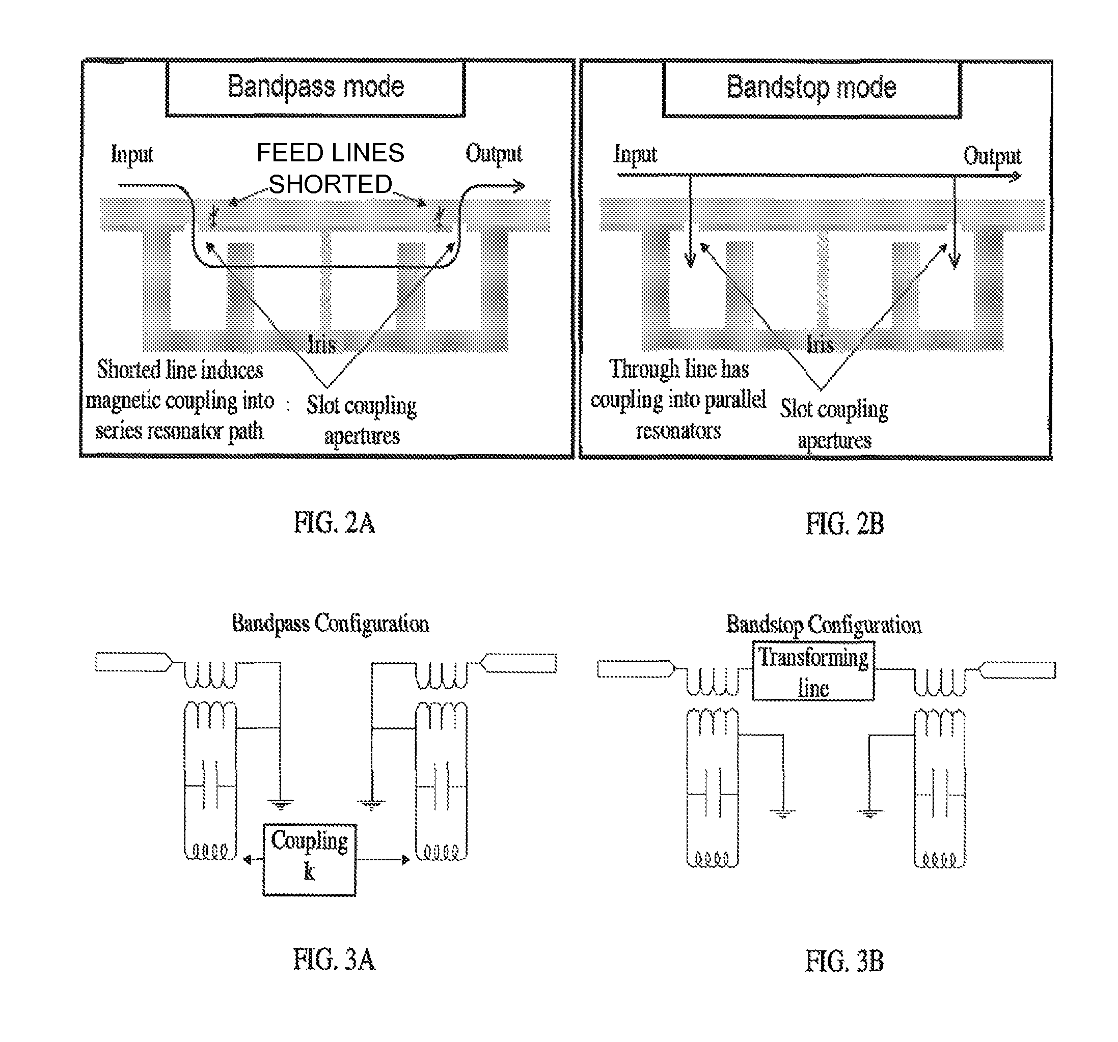
[0033]In certain embodiments of the present invention, an individual resonator is retasked to be in either bandstop or bandpass mode. This transformation is shown in FIG. 2. The device uses the same set of resonators for both bandpass mode and bandstop mode. A top layer feeds evanescent cavities in series (bandpass mode) or in shunt (bandstop mode). The equivalent circuit of the reconfigurable resonators is illus...


PUM


Abstract

A field programmable filter array with high spectral isolation and reconfigurability. A bank of resonators can be programmed at will and on the fly to give any type of filtering response. The order, type and bandwidth of the filter are electronically reconfigured. Each subset of resonators can switch between bandstop and bandpass configurations and form custom filter shapes consisting of combinations of bandstop and bandpass filters. The filter can include a unit cell of a resonator with a series of switches to enable coupling to any of its nearest neighbors. The path in which the flow of energy takes through the array of resonators is dynamic, and the filtering function which is created is dialable on demand.

Description

CROSS-REFERENCE TO RELATED APPLICATION[0001]This application claims the benefit of Provisional Patent Application No. 61 / 312,103, filed Mar. 9, 2010, which application is hereby incorporated by reference along with all references cited therein.GOVERNMENT RIGHTS[0002]This invention was made with government support under Contract / Grant No. W15P7T-06-C-P635 awarded by DARPA. The government may have certain rights in the invention.BACKGROUND OF THE INVENTION[0003]This invention relates to tunable filters of the type used in electronic communication systems, and more particularly to reconfigurable filters.[0004]Problems exist with wireless systems in the presence of high power interferers such as are encountered in electronic warfare. One typical scenario, depicted in FIG. 1, involves a military convoy transmitting high power interferers, i.e., jamming signals, while operating sensitive receivers. High power interferers can cause an RF receive chain to saturate or cause an A / D converter ...

Claims


Application Information

Patent Timeline
Patent Type & Authority Patents(United States)
IPC IPC(8): H03H7/01H01P1/20
CPCH03H7/01H01P1/2088H01P1/209H01P1/2053H01P1/20H01P1/2039
Inventor CHAPPELL, WILLIAM J.PEROULIS, DIMITRIOSLEE, JUSEOPNAGLICH, ERIC J.SIGMARSSON, HJALTI H.
Owner PURDUE RES FOUND INC
Why Eureka
Try Eureka