System and apparatus for driving a track mounted robot

a technology of track-mounted robots and drive systems, which is applied in the direction of gearing, manufacturing tools, hoisting equipment, etc., can solve the problems of excessive noise, inability to precisely position the trolley, and the drive system, so as to facilitate rapid acceleration, deceleration and precise positioning of the robot, and enhance the ability of the system

Active Publication Date: 2005-12-29
KÖRBER SUPPLY CHAIN LLC
View PDF23 Cites 6 Cited by
  • Summary
  • Abstract
  • Description
  • Claims
  • Application Information

AI Technical Summary

Benefits of technology

[0003] In accordance with the invention, a drive unit for a track mounted delivery robot includes a drive motor mounted on the robot coupled to at least one drive wheel through a motor pulley and a resilient drive belt formed from a relative soft material so as to have a high coefficient of friction. The drive wheel is positioned to engage the track to drive the robot and configured to match the profile of the track. The drive wheel and resilient belt are configured such that the belt does not substantially engage the track as the drive wheel engages the track to drive the robot. As used herein, the phrase “does not substantially engage” means that the belt does not normally contact the track, however, it does not exclude incidental contact resulting from variations in clearances and manufacturing tolerances. In order to facilitate rapid acceleration, deceleration and precise positioning of the robot, one or more track extensions are mounted on the track at selected locations. The extensions are mounted on the side of the track in locations where the resilient belt will engage the extension to provide additional driving or braking force, thereby enhancing the ability of the system to rapidly start, stop and precisely position the robot.

Problems solved by technology

In many cases, these drive systems suffer from a number of drawbacks including excessive noise, inability to precisely position the trolley for loading or unloading, and excessive component wear.
These drawbacks tend to be compounded when the unit being driven is heavy, requiring more force to accelerate, decelerate and precisely position the unit.

Method used


Image

  • System and apparatus for driving a track mounted robot
  • System and apparatus for driving a track mounted robot
  • System and apparatus for driving a track mounted robot

Examples


Embodiment Construction

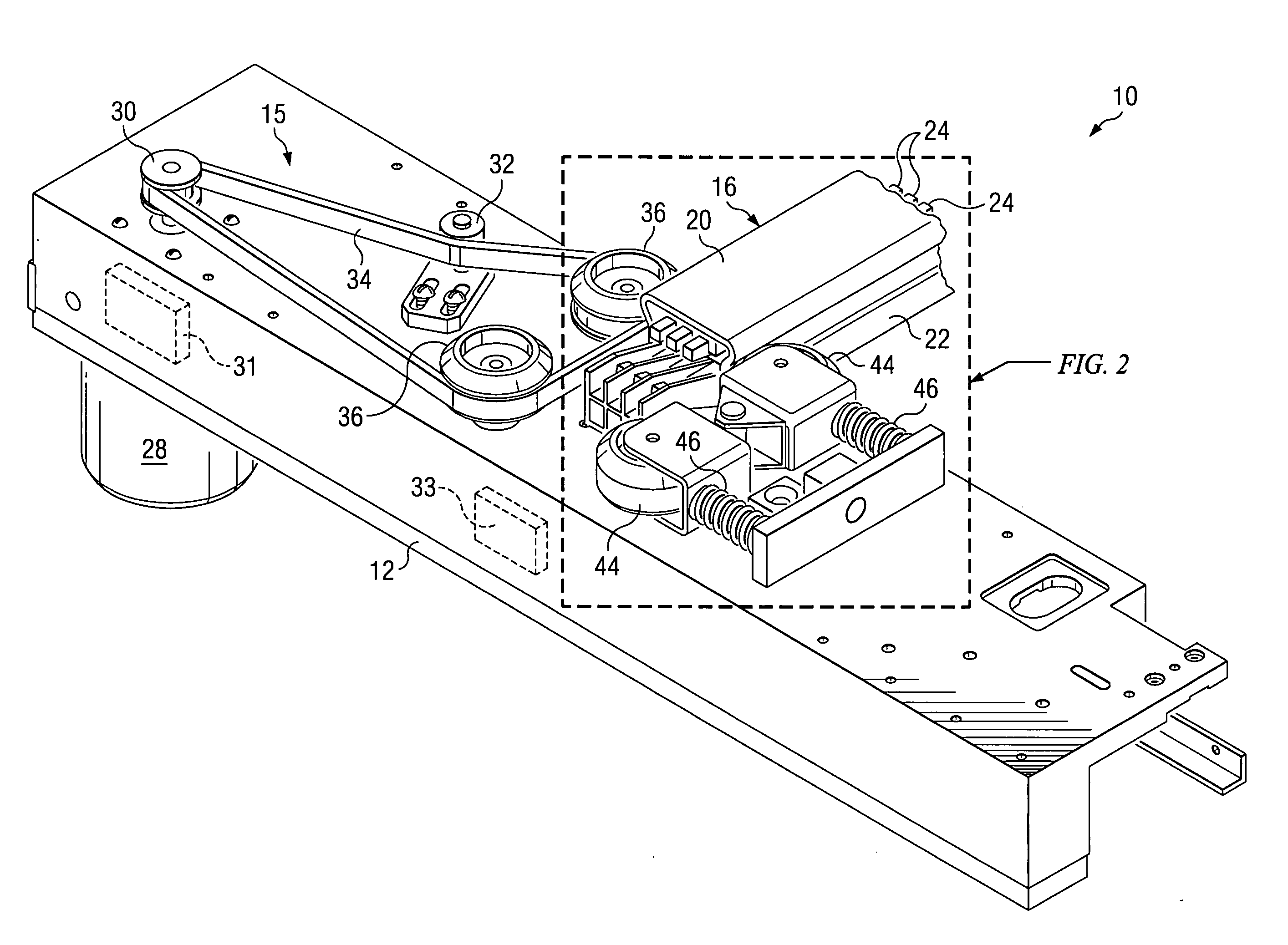
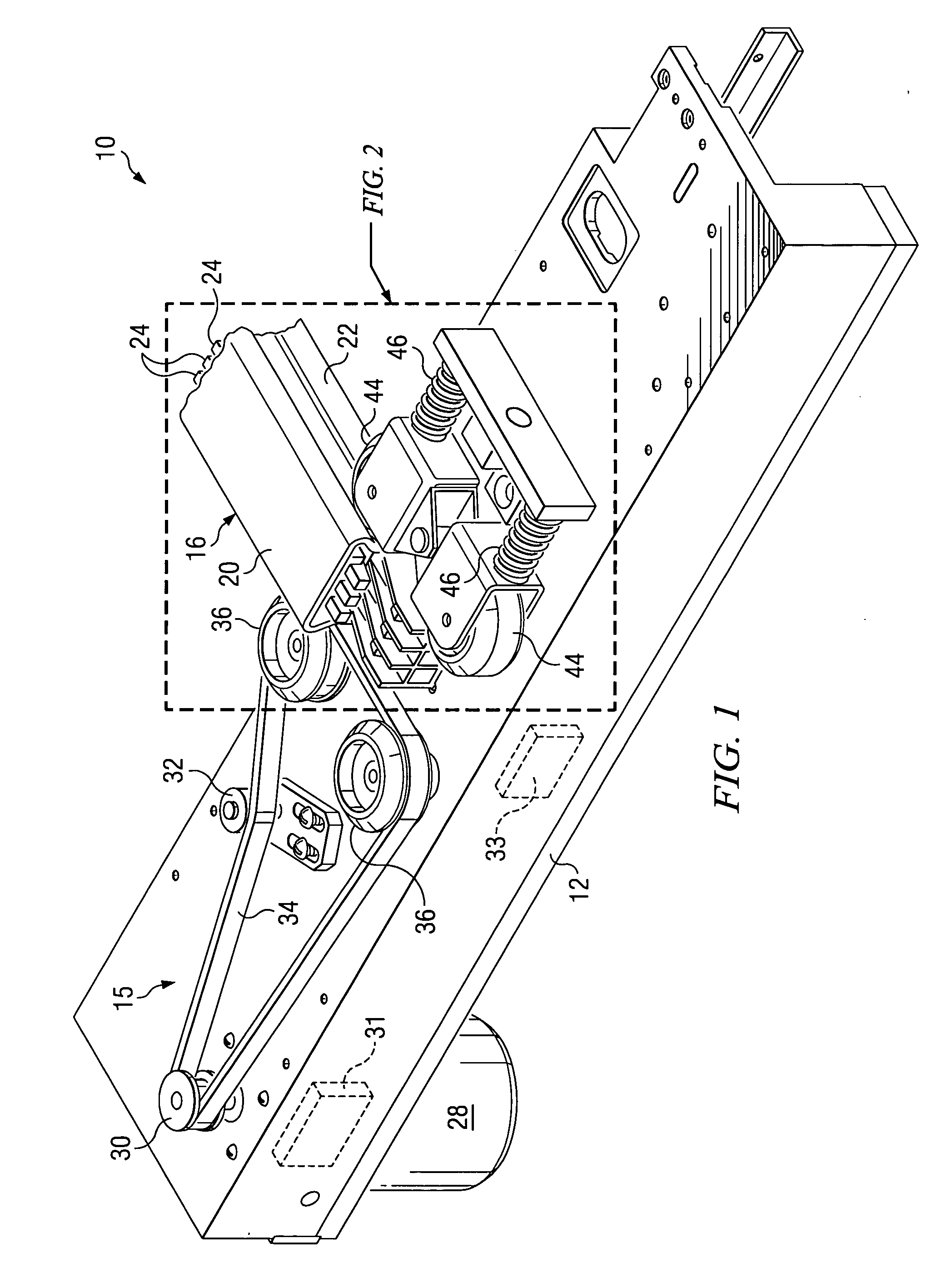
[0017] Referring to FIGS. 1-4, a delivery robot 10 configured to receive and transport articles to one of a number of selected destinations includes a frame 12 and a plurality of guide wheels 14 along the lower edge of frame 12 for supporting the robot on a shelf or similar structure (not shown) positioned below the robot as the robot travels along a track 16. Track 16 includes a flat top wall 20 and a pair of trough shaped sidewalls 22 that form a downwardly opening channel 18. One or more electrified rails 24 mounted on the inside surface of top wall 20 extend downwardly into channel 18 to provide power to robot 10. As shown, robot 10 is equipped with a plurality of shoes or brushes 26, each configured to contact an electrified rail 24 to provide power to robot 10.

[0018] Robot 10 is equipped with a drive unit 15 which includes an electric motor 28 mounted on frame 12 with a motor pulley 30, a drive belt 34 that extends around motor pulley 30 and a pair of drive wheels 36 that eng...


PUM


Abstract

A drive system for a robot includes a track including opposed sidewalls, an electrified rail positioned between the sidewalls, a shoe mounted on the robot for contacting the electrified rail providing power to the robot, a drive motor mounted on the robot, a rotating drive member, the drive member engaging the track to drive the robot when the drive motor is actuated, means for coupling the drive member to the drive motor and means for increasing the friction between the drive system and the track at selected locations along the track.

Description

TECHNICAL FIELD [0001] The invention relates to track mounted trolleys such as delivery robots and in particular to an electrically powered, belt-type drive for a track mounted delivery robot. BACKGROUND OF THE INVENTION [0002] Track mounted trolley systems are employed in a wide variety of applications including automated sorting and delivery systems in which delivery robots are utilized to receive and sort items to a variety of locations. One such system employing a plurality of track mounted robots in a sorting and delivery system is described in commonly assigned U.S. patent application Ser. No. 10 / 142,348 for an Apparatus and Method for Mail Sorting, filed Feb. 27, 2003, the disclosure which is incorporated herein by reference for all purposes. Various means of driving such track mounted units are known, including chain drives, belt drives and friction type traction drives where a wheel or pulley is rotated against the track to drive the unit. In many cases, these drive systems...

Claims


Application Information

Patent Timeline
Patent Type & Authority Applications(United States)
IPC IPC(8): B25J5/02F16H7/00F16H19/00
CPCB25J5/02F16H19/0672F16H19/06
Inventor PIPPIN, JAMES M.
Owner KÖRBER SUPPLY CHAIN LLC
Why Eureka
Try Eureka