Ultrasonic surgical apparatus with treatment modes selectable

a surgical apparatus and ultrasonic technology, applied in the field of ultrasonic surgical equipment, can solve the problems of more time and difficulty in visually confirming whether or not coagulation took place, and achieve the effect of facilitating coagulation of living tissues in a short tim

Inactive Publication Date: 2005-12-29
OLYMPUS CORP
View PDF7 Cites 386 Cited by
  • Summary
  • Abstract
  • Description
  • Claims
  • Application Information

AI Technical Summary

Benefits of technology

[0009] The present invention has been made in view of the circumstances described above, and has as its object to provide an ultrasonic surgical apparatus which reliably enables coagulation of living tissues in a short time.

Problems solved by technology

Therefore, before proceeding to incision, there has been no ample time and thus it has been difficult to visually confirm as to whether or not the coagulation satisfactorily took place.
In this manipulation, coagulation of living tissues can be visually confirmed, however, a problem has been that more time was required for the coagulation due to the low ultrasonic output.

Method used


Image

  • Ultrasonic surgical apparatus with treatment modes selectable
  • Ultrasonic surgical apparatus with treatment modes selectable
  • Ultrasonic surgical apparatus with treatment modes selectable

Examples


first embodiment

[0030] The ultrasonic surgical apparatus according to a first embodiment is described with reference to FIGS. 1 to 7.

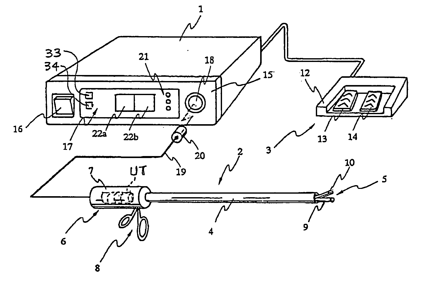
[0031] As shown in FIG. 1, the ultrasonic surgical apparatus according to the first embodiment comprises a control drive unit 1 as a device body, a hand piece 2, and a foot switch (FSW) 3 as switching means. The hand piece 2 and the foot switch 3 are physically and electrically connected to the control drive unit 1.

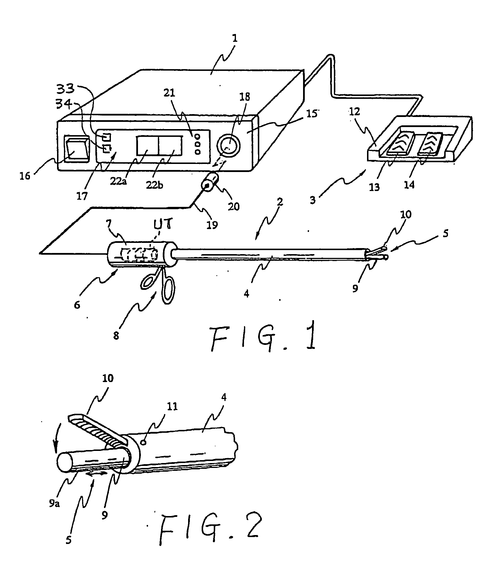
[0032] The hand piece 2 is provided with a treatment portion 5 which is disposed at the tip of an elongated and cylindrical sheath 4, and with a handling portion 6 which is disposed at the base of the sheath 4. It should be noted that, in the present embodiment, the end of the sheath 4, which is located near the control drive unit 1 is referred to as a base or base portion (or base side), and the opposite end of the sheath 4 is referred to as a tip or a tip portion (or tip side).

[0033] The handling portion 6 comprises a case 7 for accommodating an ultras...

second embodiment

[0087] A second embodiment of the ultrasonic surgical apparatus is described hereinafter with reference to FIG. 12.

[0088] In the ultrasonic surgical apparatus of the present embodiment, like or the same components as those of the first embodiment are referred to by the same reference numbers, and description therefore is omitted or simplified.

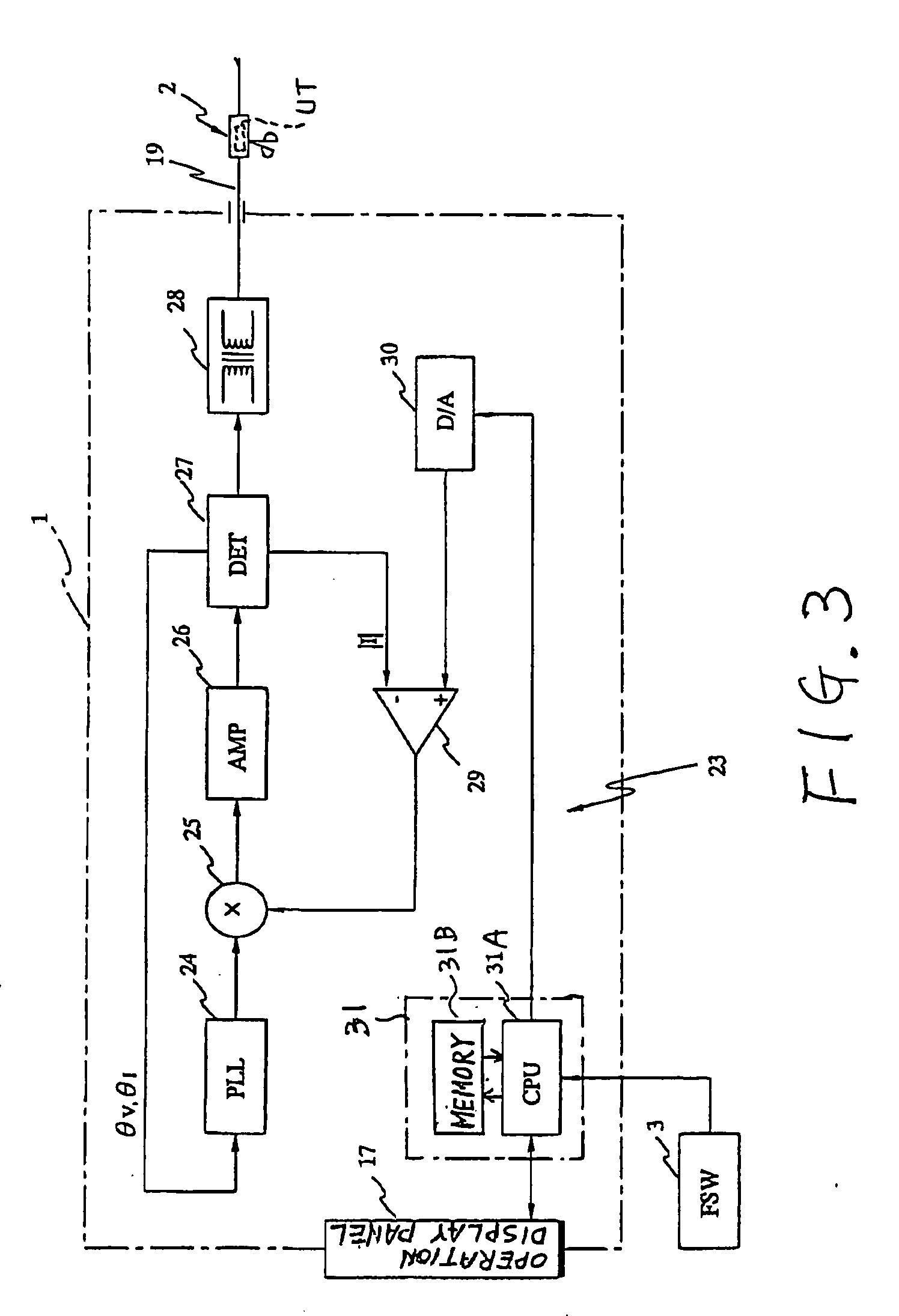
[0089]FIG. 12 shows the transducer drive circuit 23 which is loaded on the control drive unit 1 of the ultrasonic surgical apparatus.

[0090] As shown, the transducer drive circuit 23 is provided with an A / D converter 32. The A / D converter 32 is connected between an output terminal of the differential amplifier 29 and the computer 31, so that the A / D converter 32 converts output signals from the differential amplifier 29 into digital data and imparts the resultant to the computer 31.

[0091] The other portions of the configuration are the same with those described in the first embodiment.

[0092] Upon ON-operation of the power switch 16 of the c...


PUM


Abstract

An ultrasonic surgical apparatus comprises a treatment device with an ultrasonic transducer driven to generate ultrasonic vibration, an operation device outputting a signal commanding the transducer to start driving in response to an operator's operation, and a driver driving the transducer by supplying current thereto. The apparatus further comprises a controller controlling the driver. The controller controls the driver using selectively a first output control pattern and a second output control pattern. The first output control pattern is set to supply the current of a first current value under control of constant current control in response to the signal from the operation device, while the second output control pattern is set to supply the current of a second current value in response to the signal from the operation device and then the current is reduced in amount as the time counted from starting the supply elapses.

Description

CROSS REFERENCES TO RELATED APPLICATIONS [0001] The present application relates to and incorporates by reference Japanese Patent application No. 2004-184152 filed on Jun. 22, 2004. BACKGROUND OF THE INVENTION [0002] 1. Technical Field of the Invention [0003] This invention relates to an ultrasonic surgical apparatus for effecting treatment by ultrasonic vibration. [0004] 2. Related Art [0005] Ultrasonic coagulation and incision apparatuses, one type of apparatuses utilizing ultrasonic vibration and constituting surgical devices, have been used. The ultrasonic coagulation and incision apparatuses comprise an ultrasonic probe and a holder which is driven for opening and closing of the ultrasonic probe. Coagulation and incision of living tissues have thus been carried out by giving ultrasonic vibration to the ultrasonic probe in the state where the living tissues are held between the ultrasonic probe and the holder. [0006] In such a conventional ultrasonic coagulation and incision appa...

Claims


Application Information

Patent Timeline
Patent Type & Authority Applications(United States)
IPC IPC(8): A61B17/00A61B17/32
CPCA61B17/320092A61B2017/00176A61B2017/00172A61B2017/00132A61B2017/320093A61B2017/320095
Inventor KIMURA, KENICHIMASUDA, SHINYASHIMIZU, KOH
Owner OLYMPUS CORP
Why Eureka
Try Eureka