Line-marking device with positioning devices and trigger activator

a technology of positioning device and trigger activator, which is applied in the direction of measuring device, using mechanical means, instruments, etc., can solve the problem of inconvenient procedure, and achieve the effect of easy and accurate positioning and marking

Inactive Publication Date: 2006-01-05
TESSEL DAVID +1
View PDF20 Cites 14 Cited by
  • Summary
  • Abstract
  • Description
  • Claims
  • Application Information

AI Technical Summary

Benefits of technology

[0005] A line-marking device according to embodiments of the invention allows the worker (or user) to easily and accurately position and mark a line in a desired location on a wall, floor or other surface, for example, with respect to a reference such as a line or point, etc., located spaced from the location at which the desired line is to be marked, and / or at an angle with respect to the vertical, horizontal or a reference, and / or at a desired distance from a reference, etc. The invention also provides, a trigger mechanism for snapping a marking filament of the marking device against the surface to be marked. The device is particularly useful for amateur and professional carpenters, kitchen cabinet installers, tile setters and so forth.
[0007] In one embodiment, a self-supporting member or strip with distance notation thereon may be mounted to the device to be displaceable relative thereto to be used in the positioning of the marking device and / or filament at a given distance from a reference. In this embodiment, use of the device with one hand is facilitated because, unlike a tape which is prone to sagging and bending, the self-supporting member can be maintained in a straight position. Also, the self-supporting member may be fixed and used for repetitive measurements without having to retract and extend it. As an aid to this use, a tab is appended flush with the end of the self-supporting member so that when such member rests against the surface being measured, the tab abuts an end of such surface.

Problems solved by technology

In any event, the procedure is inconvenient.

Method used


Image

  • Line-marking device with positioning devices and trigger activator
  • Line-marking device with positioning devices and trigger activator
  • Line-marking device with positioning devices and trigger activator

Examples


Embodiment Construction

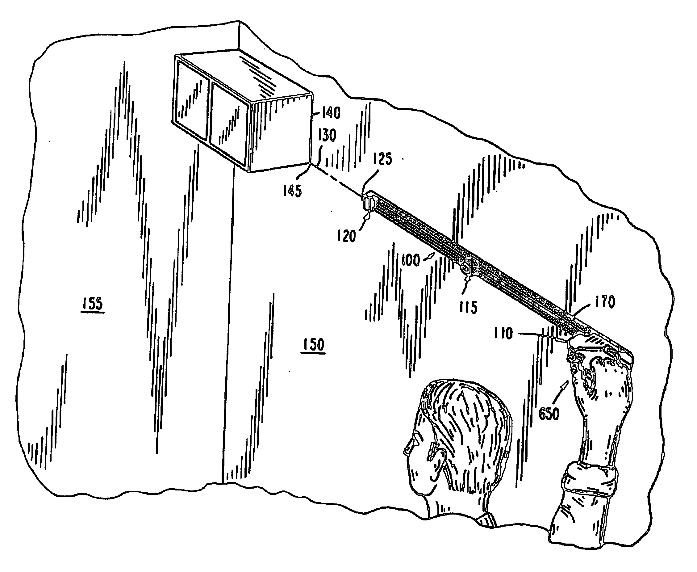
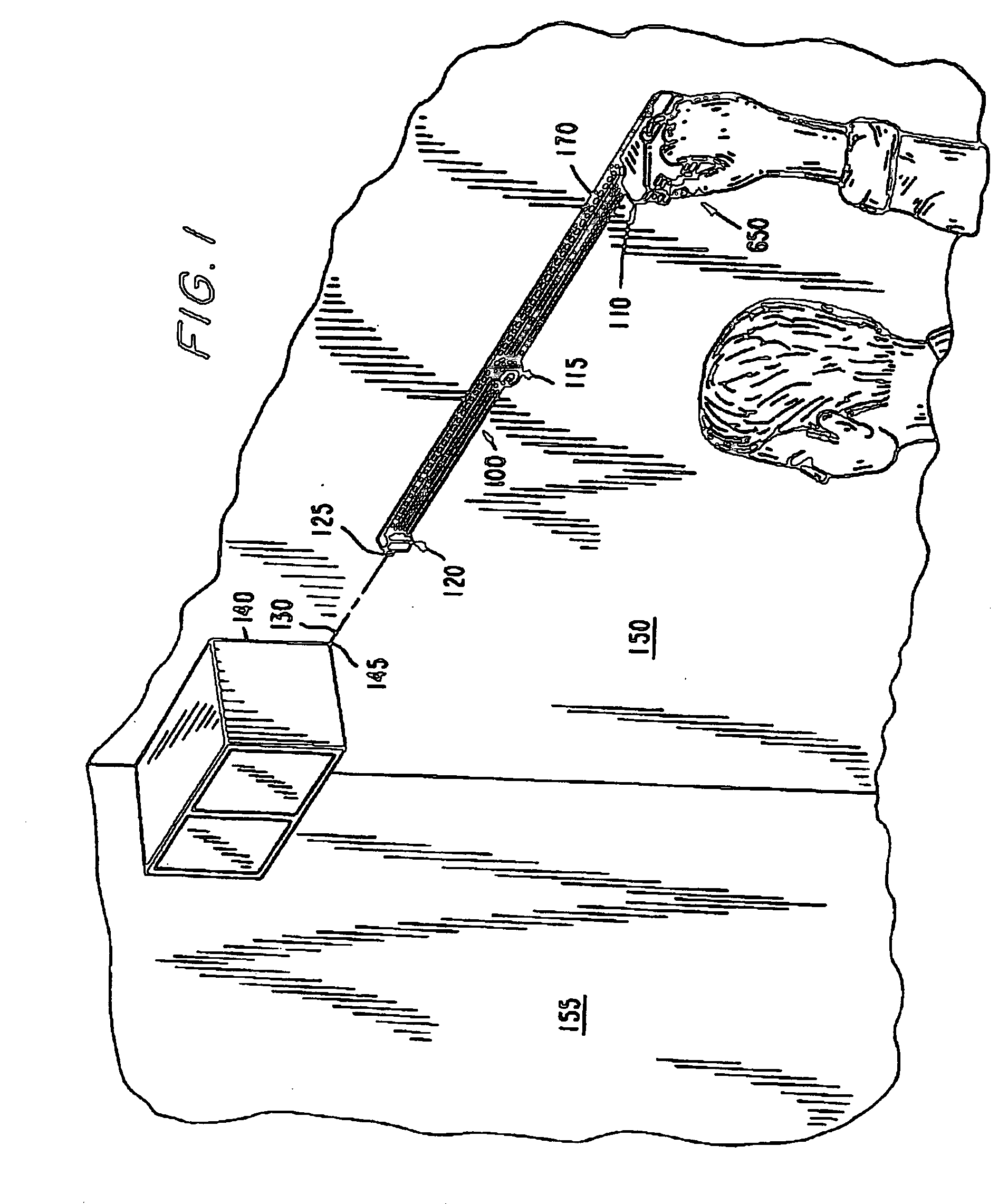
[0036]FIG. 1 depicts an embodiment of a line-marking device, shown generally at 100, that includes a laser device 125 in accordance with the invention. The line-marking device 100 may be used to apply a line on interior and exterior surfaces of construction such as drywall, panelling, plywood, concrete and the like, and on surfaces of paper, cloth, metal, plastic etc., of various items for artistic purposes and other non-technical purposes, as well as for technical and architectural purposes.

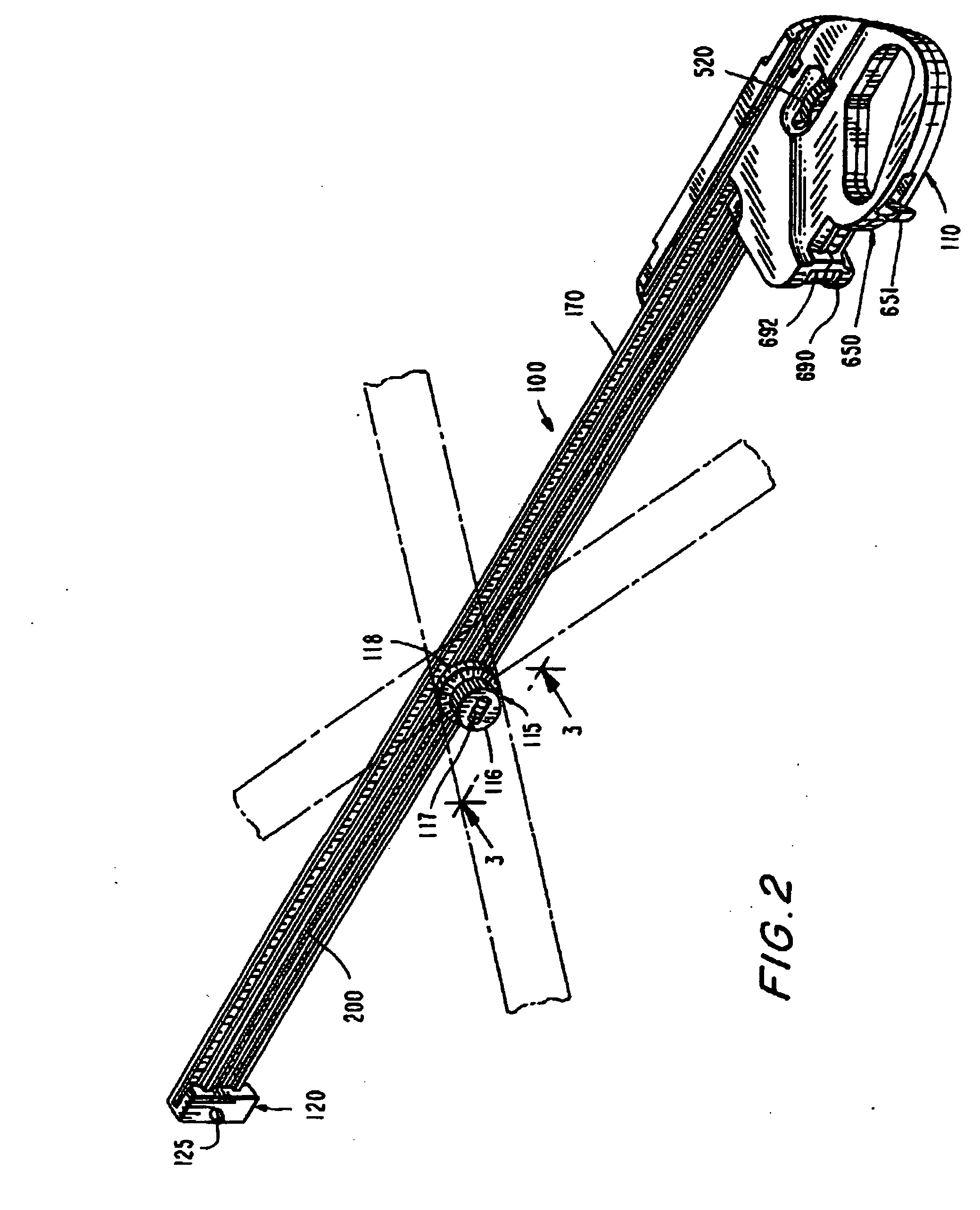
[0037] As illustrated in FIG. 1, the line-marking device 100 allows a worker to easily apply a line relative to a reference such as the bottom of a cabinet. The line-marking device 100 includes an elongated frame 170, a marking filament 200 (FIG. 2) that is held taut by the frame 170, and a handle 110 that is secured to the frame 170 to operate the line-marking device 100. Some of these components may be seen to be similar to those in the aforementioned U.S. Pat. No. 5,699,622. A laser device (...


PUM


Abstract

A line-marking device (100) includes a chalk line (200) that is held in an elongated frame (170). A worker can position and align the device, then snap the line (200) using a manually operated trigger (650) to leave a mark on a surface (530), such as a wall or floor. An adjustable level device (115) on the frame (170) can be rotated to dial a desired angle for the line. The adjustable level device (115) may be provided in an angle setting device independently of the line-marking device. A laser device (125) may be carried at the tip (120) of (or elsewhere on) the frame (170) to allow the chalk line to be aligned with a reference mark (145). Respective markings (176, 177) on edge regions of rails (171, 174) of the frame (170) may indicate an angular setting of a guide bar (500), or, a protractor (810, 810a) may indicate-the angular setting. The guide bar (500) may be relocated facing away from the filament (200) and used as an angle finding device. A retractable tape measure (1500) carried by the device enables a worker to measure distances from the chalk line.

Description

CROSS REFERENCE TO RELATED APPLICATIONS [0001] This application claims priority of application Ser. No. 10 / 421,553, titled Line-Marking Device with Positioning Devices and Trigger Activator, which was filed on Apr. 23, 2003, the disclosure of which is incorporated herein by reference in its entirety.BACKGROUND OF THE INVENTION [0002] The present invention relates to a hand-held device for marking a chalk line for use in construction, home improvement and the like. [0003] Conventional chalk line-marking devices employ a chalk line that is wound up around a spool within a case. During use, the chalk line is extended and held taut near the surface to be marked. Typically, this requires two workers—one to hold the end of the chalk line and one to hold the case. The line is then grasped and released by one of the workers so that it snaps back toward the surface, thereby depositing a chalk line. Or, one worker may devise a way to secure one end of the line using a weight or the like. In a...

Claims


Application Information

Patent Timeline
Patent Type & Authority Applications(United States)
IPC IPC(8): G01B3/14B44DB44D3/38
CPCB44D3/38
Inventor TESSEL, DAVIDUMBRO, GERALD G.
Owner TESSEL DAVID
Why Eureka
Try Eureka