
Window shade with conical winding shaft

a technology of winding shaft and window shade, which is applied in the direction of curtain accessories, curtain suspension devices, applications, etc., can solve the problems of large gap to remain into which objects may fall, inability to extend parallel, and high risk of objects being dropped into the interior of the door through the gap, etc., to achieve the effect of being handled more easily

Inactive Publication Date: 2006-01-05
BOS
View PDF13 Cites 11 Cited by
  • Summary
  • Abstract
  • Description
  • Claims
  • Application Information

AI Technical Summary

Benefits of technology

[0007] In view of the foregoing, a general object of the invention is to develop a window shade for motor vehicles that can be handled more easily.
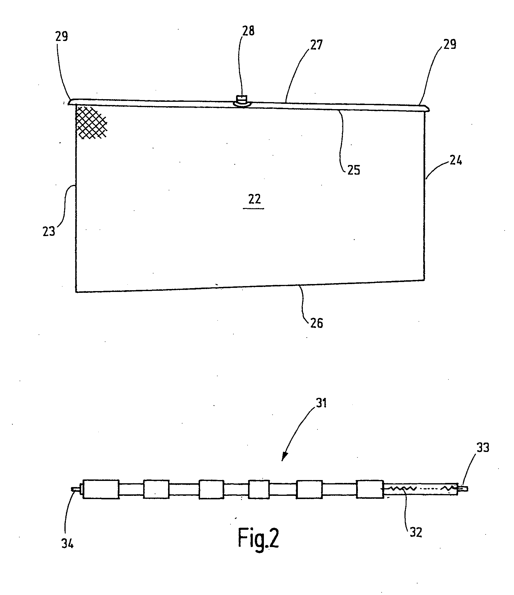
[0010] Depending on the conicality and length of the winding shaft, the individual wrappings can have an axial length between 10% and 30% of the length of the winding shaft. The tip of the imaginary cone is directly formed by the core section that is free of wrappings. The steps created in this manner are so small that they cause no problems during the winding operation. It is also possible to space apart the wrappings in order to lower the material costs.

Problems solved by technology

However, this section does not extend parallel to the lower edge due to the shape of the car body.
However, if the side window is shaded by a window shade, one encounters the problem that the upper edge of the side window shade either projects beyond the lower edge of the window or causes a large gap to remain into which objects may fall.
This is of particular importance because children are frequently seated on the rear seats of motorcars and thus the risk of objects being dropped into the interior of the door through the gap is accordingly high.
Such an arrangement is usually not feasible, however, due to the space conditions in the interior of a car door.
However, this arrangement is limited to applications in which the short lateral edge that forms an extension of the front lateral edge of the window shade, web and thus the other leg of the triangle is shorter than the circumference of the winding shaft.
Otherwise, the point would uncontrollably fold over during the wind up process at the assembly site.
In addition, the strip shaped blanks are difficult to handle during assembly due to the limited reproducibility.
The lack of rigidity in the material used for the window shade web additionally complicates the situation.

Method used


Image

  • Window shade with conical winding shaft
  • Window shade with conical winding shaft
  • Window shade with conical winding shaft

Examples


Embodiment Construction

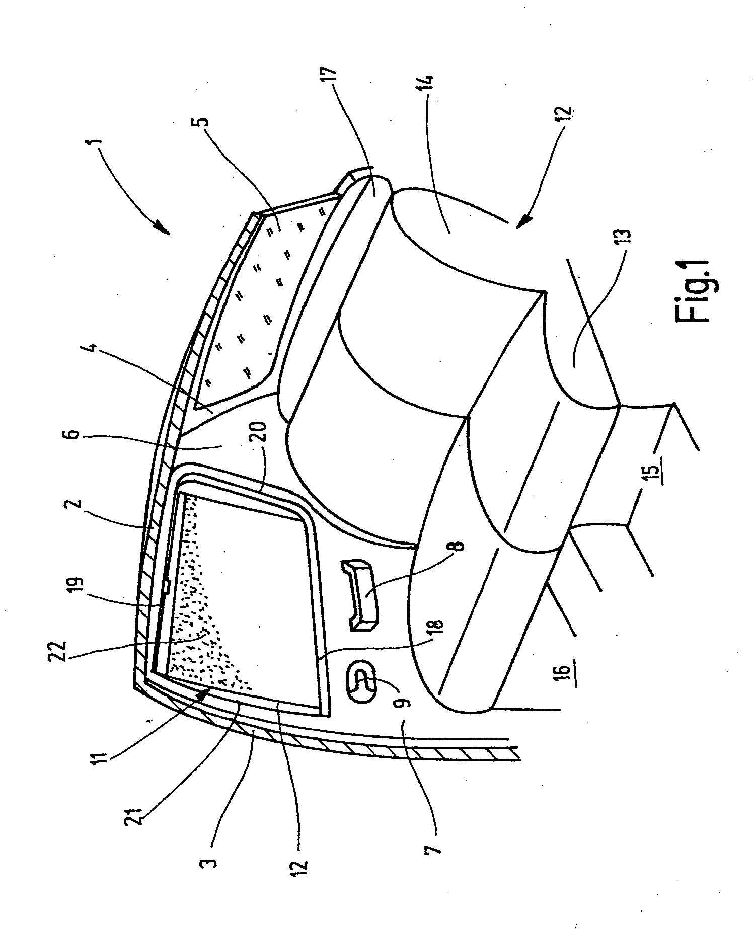
[0018] A cut off rear section of a motor car is shown in FIG. 1. FIG. 1 provides a view of the right inner side that is the mirror image of the not shown left inner side. FIG. I is simplified in certain respects, e.g., interior structures of the car body such as reinforcements, mounting elements and the like are not shown because they are not essential for comprehending the invention. In other respects, the terms “right,”“left,”“front” and “rear” refer to the conventional terminology used in automotive engineering.

[0019] The illustrated car body section 1 includes a roof 2, from which a B column 3 laterally extends to a floor assembly. A corresponding B column is also provided on the left side of the vehicle (not shown). At its rear edge, the roof 2 transitions into a tailgate 4 that is conventionally hinged to the lower edge of the roof 2. A rear window 5 is accommodated in the tailgate 4. The tailgate 4 or the opening accommodating the tailgate borders on a C column 6. A right re...


PUM


Abstract

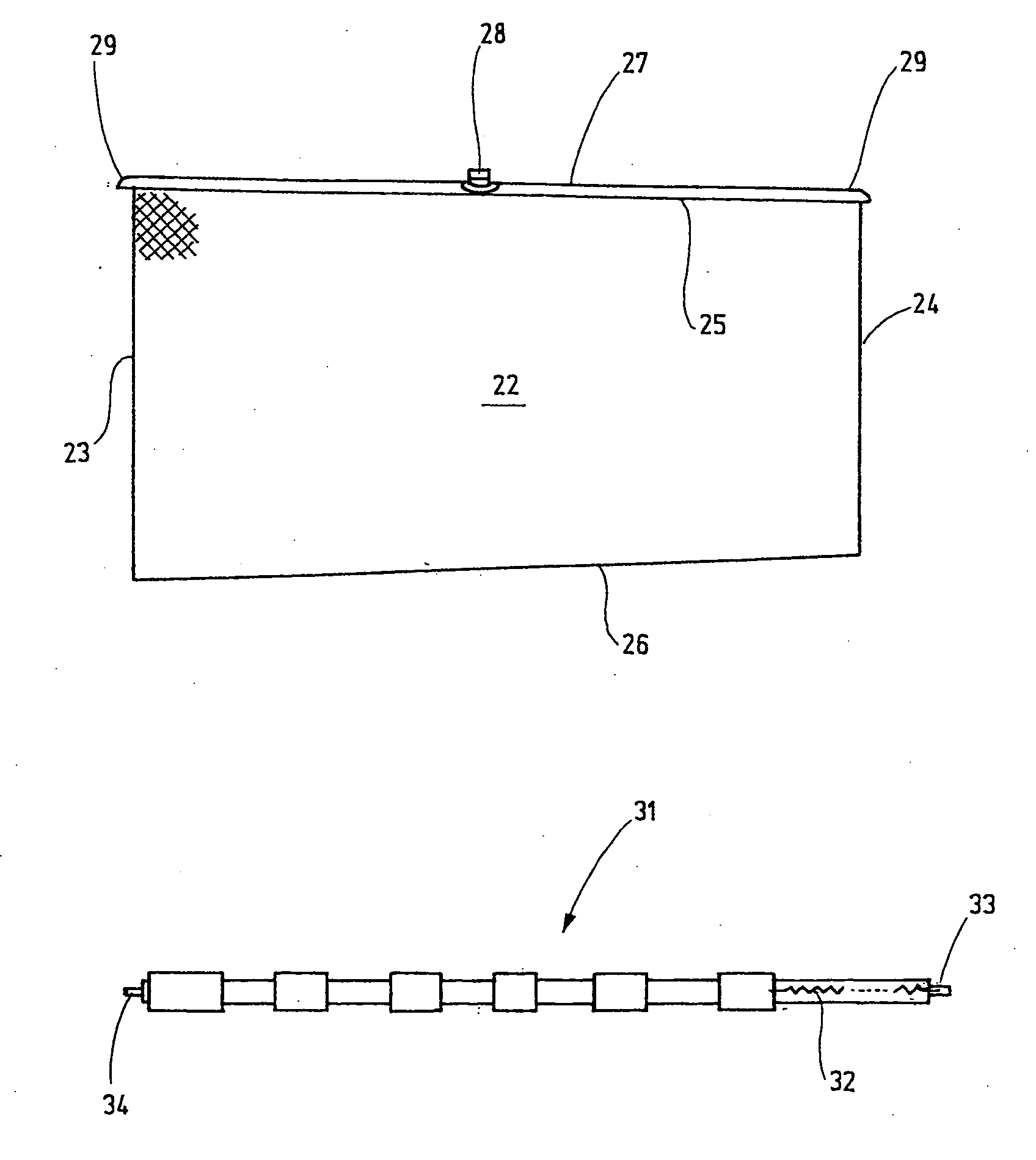
A window shade assembly for motor vehicles is provided. The window shade assembly includes a window shade element that is cut into a trapezoidal shape in order to be optimally adapted to the shape of the corresponding window. The winding shaft for this window shade web resembles a truncated cone that is approximated by means of a cylindrical core with wrappings applied thereon.

Description

BACKGROUND OF THE INVENTION [0001] Motorcars are typically equipped with additional side windows in the rear area of the car body. These side windows are either directly integrated into the car body or form part of rear side doors. If such a window is arranged in a side door, it is typically divided into two sections, namely an approximately trapezoidal section and a triangular section. The trapezoidal section is designed in this fashion because the side window pane can be lowered in this region in order to open the window. The upper edge of the side window is almost always composed of an essentially straight section and a curved section in order to prevent an abrupt transition into the triangular region. The upper edge of the quadrangular section can be considered to be roughly straight. However, this section does not extend parallel to the lower edge due to the shape of the car body. When the side window pane is lowered, this results in the upper edge of the window pane still bein...

Claims


Application Information

Patent Timeline
Patent Type & Authority Applications(United States)
IPC IPC(8): B60J3/00B60J1/20
CPCB60J1/205B60J3/02
Inventor GANSER, KONRAD WILHELMSCHLECHT, WERNER P.
Owner BOS
Learn More